Installation and Adjustment
EN
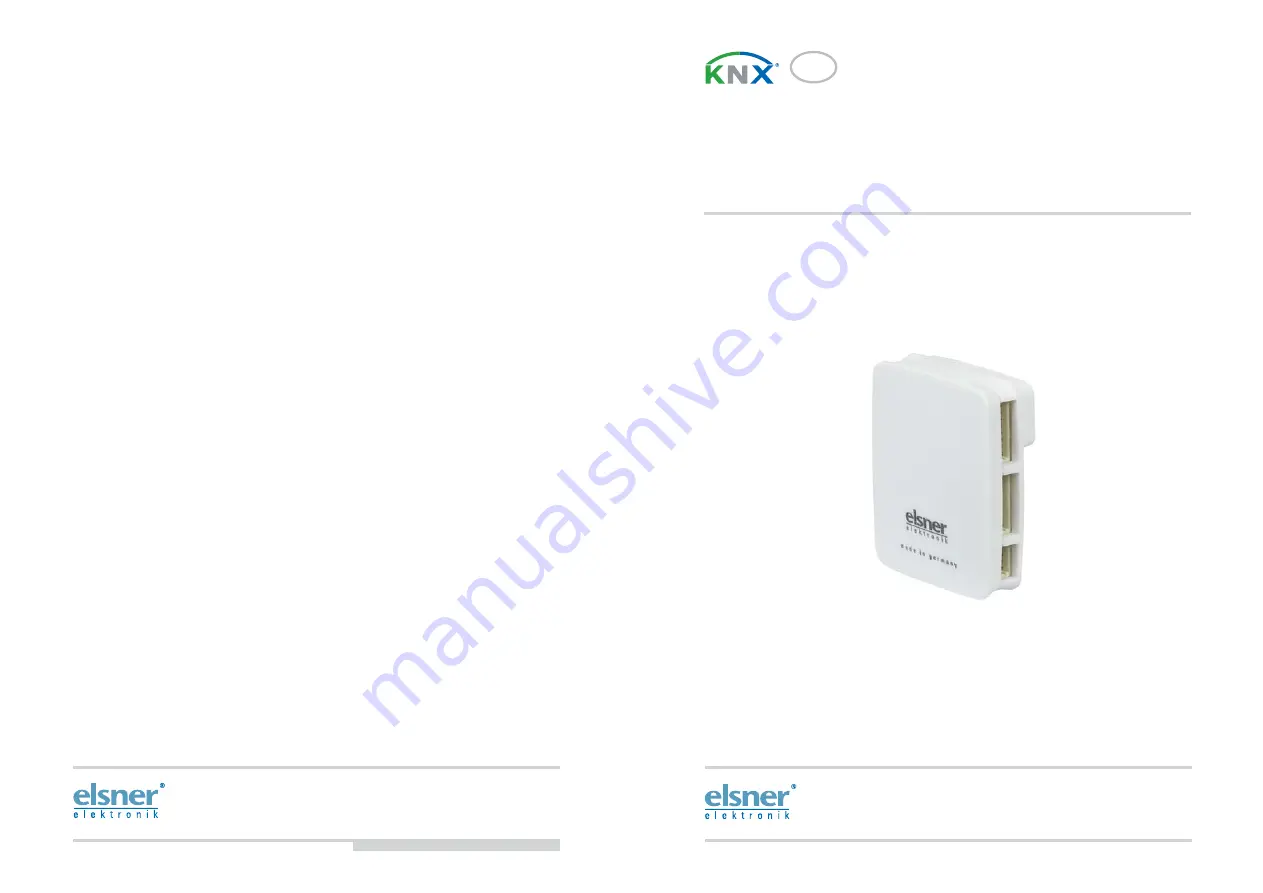
KNX B8-TH
Interface
Item number 70249
Elsner Elektronik GmbH
Control and Automation Technology
Sohlengrund 16
75395 Ostelsheim
Phone +49 (0) 70 33/ 30945-0
[email protected]
Germany Fax
+49 (0) 70 33 /30945-20
www.elsner-elektronik.de
Technical support: +49 (0) 70 33 / 30 945-250


