Page 24
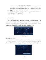
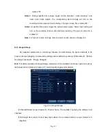
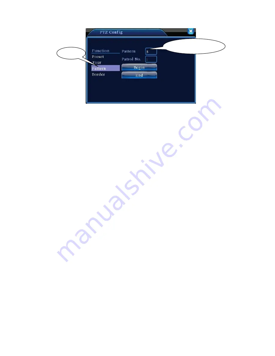
Figure 3.14 Trace Setup
2) Trace call-up
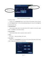
In Figure 3.10, click
Page Switch
button to enter PTZ control interface as shown in Figure 3.12.
Click
Trace
button and enter trace number in
Value Input box
. PTZ will operate following the route
setup. Click arrow keys to stop.
4. Boundary Line Scanning
Set up a horizontal route and call up line scan to have PTZ run repeatedly on given route.
1) Line Scan Setup
Follow below steps to set up a section of horizontal curve as the trace for PTZ search:
Step 1: In Figure 3.10, use arrow keys to rotate the PTZ to the desired preset direction. Click
Set
key to enter Figure 3.15. Select the left boundary and return to Figure 3.10;
Step 2: Use arrow keys to select the desired position. Click
Set
to enter Figure 3.15 and select
the right boundary. Then return to Figure 3.10;
Step 3: Complete the setting for left and right boundaries of the position.
Note:
When left and right boundaries are on the same horizontal level, PTZ will rotate counter
clockwise from left boundary to the right;
If they are not on the same level, PTZ uses the end of the horizontal trace connecting to the left
boundary as the right boundary point and rotate anticlockwise from the left to the right.
Trace value input box
Trace

