Technical Manual Cold Storage Controllers TKP / TKC x130 - x140
Page 11
Real Time Clock
The built-in real time clock is buffered for a period
where mains voltage is switched off (3 years up to
softw.vers. 6.9, appr. 10 days from softw.vers. 7.00).
Date and Time can be set on the 'mode page'.
Factory set is a GMT +01:00 ('timezone offset'=
60 min.), which is valid for mid europe. If the con-
troller is used in other zones, the values can be
readjusted.
Summer/Winter Time (Daylight Saving Time)
Switching / Time Zones
An automatic summer / winter switching (parameter
„
summer/ winter
“) considers the current EU-rules
from 1996 (EU 96), but it can also switched off or
set as necessary.
Variable Time Zones
By parameter "
timezone offset
" the summer/winter
time switching can be adapted as necessary.
"
summerOn month
" (fact.set: march, 3rd)
The month before summertime begins
"
summerOn day
"
(fact.set: 0, sunday)
The day of the week where summertime begins
"summerOn
x-day
"
(fact.set: 5, last sunday)
The day no. x in the month set with
"summerOn day
"
"
summerOn hour
"
(fact set: 2, (2:00 am))
The hour of the beginning of the summertime
"
summerOff month
" (fact.set: october, 10th)
The month of the end of the summertime
"
summerOff day
"
(fact.set: 0, monday)
The day of the week where summertime ends
"
summerOff x-day
"
(fact.set: 5, last sunday)
The day no. x in the month set with
"
summerOff day
"
"
summerOff hour
"
(fact.set: 2, 2:00 am)
The hour of the end of the summertime
All time settings are preset in winter time
.
Analog Output
The controller contains an analog output which
can be used for regulation or to provide a remote
display with an actual value image. The signal
is available as a DC-Voltage or a DC-Current-
Signal.
Parameter „
analog value
“ (actual page) shows the
current output signal as a %-part of the selected
range, "
analog function
" (assignment page) de-
termines the behaviour of the output:
Test functions (output delivers fixed values only)
0V
= voltage = 0V, current = 0 mA
4mA
= voltage = 2V, current = 4 mA
10V/20mA
= voltage = 10V, current = 20mA
Transmission of actual values to remote displays
or similar
act.img 0-10V
=
The outputs provide an image of the value of
refrig.sensor 1.
voltage: -50°C = 0V, +100°C = 10V
current: -50°C = 0mA, +100°C = 20mA
act.img 4-20mA
=
The outputs provide an image of the value of
refrig.sensor 1. .............
voltage: -50°C = 2V, +100°C = 10V
current: -50°C = 4mA, +100°C = 20mA
Control with the analog output signal (PI-con-
trol)
PID-T1 0-10V
=
This PID-controller with 0-10V DC-signal is
assigned to cooling circuit 1. The output signal
represents an addition of the components
P, I, D and T1.
PID-T1 4-20mA
=
This PID-controller with 4/20mA-signal is
assigned to cooling circuit 1. The output signal
represents an addition of the components
P, I, D and T1.
PID-T1 10-0V
=
PID-controller like above, but with inverted
voltage output (rising temperature = falling
voltage).
PID-T1 20-4mA
=
PID-controller like above, but with inverted
4/20 mA-output (rising temperature = falling
current)
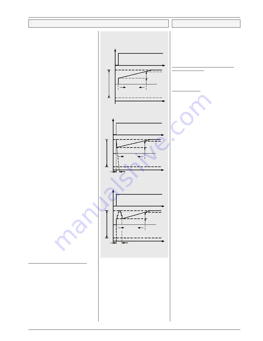
To adapt the controller to the process use the
following parameters:
" PID propor band"
.....situated symmetrically
to '
setpoint Ch 1
'
" PID integr time"
.......integral time (I-part)
" PID attack time"
.......derivative time (D-part)
" PID delay"
............actuator response time
(T1-part)
How to affect the analog output manually
For certain operations it might be usefull to affect
the output signal manually. Therefore the function
„
analog value
“ (assignment page) can be assigned
to one of the digital inputs.
Applying mains phase to a configured digital input
the analog output will be forced to the value (in %)
that is programmed by „
opto->analogout
“ (setpoint
page). So e.g. a connected valve drive will be set
to a specific position.
"
function Opto. x
" (Assignment Page)
= configuration of the digital (OK) input for
this function
"
opto->analog val.
" (Setpoint Page)
= value of the output signal in %/V/mA, if
the digital (OK) input has been activated
PI-control, D and T1-parts de-activated
PID-control, T1-part de-activated
PID-control, with T1-low-pass filter
Control Characteristic
P ID
integral tim e
pr
op
or
tio
na
l b
an
d
m in.
ou
tp
ut
se
tp
oin
t-
de
via
tio
n
m ax.
5V resp. 12m A
P -part
t
I-part
t
t
P ID attack tim e
P ID
inte g ral tim e
pr
op
or
tio
na
l b
an
d
m in.
ou
tp
ut
5 V re sp . 1 2 m A
P -p art
I-p art
se
tp
oin
t-
de
via
tio
n
m ax.
t
t
P ID d e lay
pr
op
or
tio
na
l b
an
d
m in.
ou
tp
ut
5 V re sp . 1 2 m A
P ID
inte g ral tim e
P -p art
I-p art
se
tp
oin
t-
de
via
tio
n
m ax.
t


