0420 Roto-Jet
9
OPERATION (CONT.)
Open the foot switch storage compartment and remove the foot switch, “O” ring, rubber hose washer
and the air hose “quick disconnect” fitting.
Position the foot switch hose in the cutout provided before closing compartment lid.
Install the quick disconnect to an air hose capable of withstanding 100 psi (6.89 Bar-Metric).
The hose should have an inside diameter of 1/2” (13mm).
Place the rubber hose washer in the water hose connection of the machine. This is a one time
operation. The rubber washer can remain in this connection and does not require removal after use.
Connect a standard garden hose to the 3/4” water hose connection of the machine. The machine is
designed for “Municipal” water pressure only, Max 100 psi (6.89 Bar-Metric). DO NOT connect the
water connection to a “High Pressure” source. Water is important to the cleaning process as it flushes
away deposits cleaned from the tube and helps to lubricate and cool the flexshaft.
Position the “O” ring in the recess of the flexshaft connection manifold.
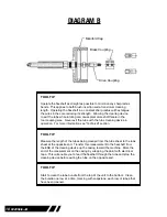
Prepare the flexshaft by loosening the four (4) set screws located in the brass locking sleeve using
a 3/32” Allen wrench. Thread the breakaway or solid square drive into the coupling adapter that
is swaged on the core of the flexshaft. Position the brass locking sleeve equally over the coupling
adapter and the breakaway or solid square drive. Firmly tighten the four (4) Allen set screws. (See
Diagram B page 8)
Insert the square drive into the manifold of the machine. Rotate the flexshaft by hand to properly seat
the square drive of the flexshaft into the manifold. Thread the brass manifold cap onto the manifold of
the machine and firmly hand tighten.
Attach the chosen cleaning device to the tool coupling swaged to the core of the flexshaft at the
opposite end from the manifold connection and firmly tighten the device. Connect the appropriate air
pressure source to the machine. For more information see “Air Supply” section.
Turn on the water supply.
Layout the flexshaft as straight as possible. DO NOT start the machine with the flexshaft in a coiled
position.
Depress the foot switch. Move the throttle valve located next to the air supply connection slowly until
the air motor starts to turn the flexshaft. Adjust this valve to the desired RPM for the cleaning device
and flexshaft being used. At the same time, water will pass through the machine and out the end of
the flexshaft casing near the cleaning device. Remove your foot from the foot switch and both the
water and rotation of the shaft will stop. Restart the machine and observe the water output from the
end of the flexshaft casing. A constant stream of water should be discharged from the casing as the
core rotates. If no water is discharged from the flexshaft, check the hose and hose connection for any
“kinks” that would restrict water flow. Depress the foot switch again and observe the water flow from
the end of the flexshaft. If no water is discharged, discontinue use of the machine and contact an
Elliott service facility.
Summary of Contents for Roto-Jet 0420
Page 2: ......
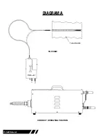
Page 8: ...8 0420 Roto Jet DIAGRAM A Tube Bundle Roto Jet TOP VIEW CORRECT OPERATING POSITION...
Page 19: ...0420 Roto Jet 19 NOTES...
Page 23: ...0420 Roto Jet 23...
Page 25: ......
Page 26: ......

