SHT-6G
2/4
PRG
OK
+
_
OK
OK
Auto
Prog
Prog
Prog
+
_
Prog
Prog
Prog
Prog
ESPAnOL
Prog
Prog
ESC
Prog
PRG
+
_
+ _
OK
ESC
ESC
CR2032
+
Technical parameters
A1 - A2
AC 100-240V; DC 140-340V (AC 50-60 Hz)
5 VA / 2 W
4.2 W
-15 %; +10 %
1x changeover (AgSnO
2
)
16 A / AC1
4000 VA / AC1, 384 W / DC
30 A / < 3 s
250 V AC / 24 V DC
30.000.000 ops.
100.000 ops.
up to 3 years
max. ± 1 s / day at 23 °C (73 °F)
1 min.
min. 10 years
100
daily, yearly (up to year 2099)
LCD display, with back light
-10.. +55 °C (14 to 131 °F)
-30.. +70 °C (-22 °F to 158 °F)
4 kV (supply - output)
3.3 kV (supply - receiver)
any
DIN rail EN 60715
IP10 terminals,
IP40 from the front panel
III.
2
max. 1x 2.5, max. 2x 1.5/
with sleeve max.1x 1.5
90 x 35 x 64 mm (3.5˝ x 1.4˝ x 2.5˝)
114 g (4 oz.) - without battery
EN 61812-1
Supply terminals:
Supply voltage:
Burden (max.):
Max. dissipated power
(Un + terminals):
Supply voltage tolerance:
Output
Number of contacts:
Rated current:
Switching capacity:
Peak current:
Switching voltage:
Mechanical life:
Electrical life (AC1):
Time circuit
Real time back-up:
Accuracy
- without GPS receiver:
Minimum interval:
Data stored for:
Program circuit
Number of memory places:
Program:
Data readout:
Other information
Operating temperature:
Storage temperature:
Electrical strength:
Operating position:
Mounting:
Protection degree:
Overvoltage category:
Pollution degree:
Max. cable size (mm
2
):
Dimensions:
Weight
Standards:
Warning
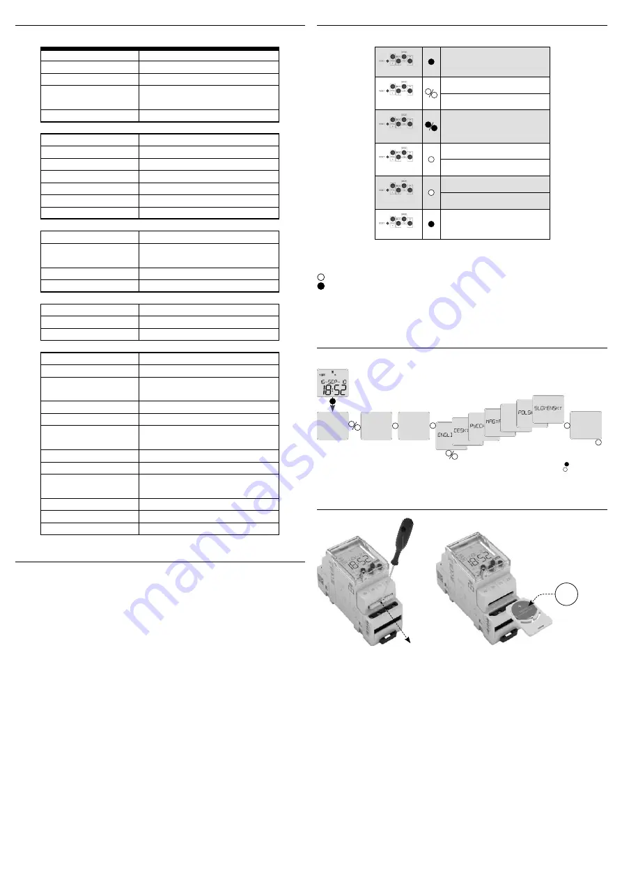
Language settings
language
selection
options
- long press (>1s)
- short press (<1s)
time/date
options
language
language
Control description
entrance into programming menu
browsing in menu
setting of values
quick shifting during setting of
values
entrance into required menu
confi rmation
one level up
a step back
back to the starting menu
Device diff ers short and long button press.
In the manual marked as:
- short button press (< 1s)
- long button press (> 1s)
After 30s of inactivity (from the last press of any button) will device automatically returns into
starting menu.
Battery replacement
You can change the battery without disassembling the device.
- remove the plug-in module with the battery
- replace the original battery
- enter a new battery so that its upper edge (+) lines up with the plug-in module
- slide the plug-in module in the device and pay attention to polarity (+ up)
Device is constructed for connection in 1-phase main alternating current voltage AC 100-240V
or DC 140-340V and must be installed according to norms valid in the state of application.
Connection according to the details in this direction. Installation, connection, setting
and servicing should be installed by qualifi ed electrician staff only, who has learnt these
instruction and functions of the device. This device contains protection against overvoltage
peaks and disturbancies in supply. For correct function of the protection of this device there
must be suitable protections of higher degree (A, B, C) installed in front of them. According to
standards elimination of disturbancies must be ensured. Before installation the main switch
must be in position “OFF” and the device should be de-energized. Don´t install the device to
sources of excessive electro-magnetic interfe rence. By correct installation ensure ideal air
circulation so in case of permanent operation and higher ambient temperature the maximal
operating temperature of the device is not exceeded. For installation and setting use screw-
driver cca 2 mm. The device is fully-electronic - installation should be carried out according to
this fact. Non-problematic function depends also on the way of transportation, storing and
handling. In case of any signs of destruction, deformation, non-function or missing part, don´t
install and claim at your seller it is possible to dismount the device after its lifetime, recycle, or
store in protective dump.
No product circuits, including sensor circuits, can be considered as ELVs.
Cable shield to the sensor, fulfi lls a functional purpose in terms of EMC does not fulfi ll any
protection or safety function and it is not associated with any EP protection. It is not possible
to touch the shield as well as the other product wiring circuits!
Security against electric shock is ensured by reinforced insulation product, cable, sensors and
their correct and professional installation.


