Page 8
M1XRFTWM Installation Manual
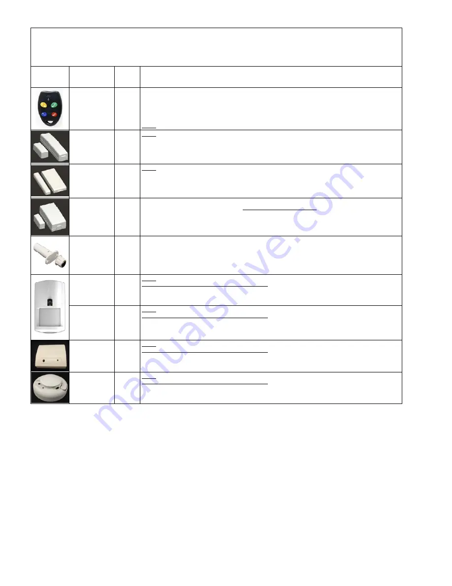
Elk 6000 Series Wireless Sensors
†
Not evaluated by UL
Elk6021
†
Mini Window
Sensor,
No Tamper
Loop # = 2 This sensor has a built-in reed switch and provides a single zone (input). When enrolled into a factory
defaulted zone location the M1 should recognize this sensor on the default loop value of 0. I.E. It should not be necessary
to change (reprogram) the Loop from 0 to 2. However if this sensor is being enrolled into a location previously occupied by
another sensor, care must be taken to be certain the Loop gets changed to Loop # 2 or else the sensor may not operate.
Elk6010
†
Keychain Remote
(FOB),
4 buttons with
System Status
Inquiry
Elk6022
†
Universal 3-Zone
Dr/Wnd Sensor,
1 Reed + 2 Aux.,
Front/Back Tamper
Elk6020
†
Slim Door &
Window Sensor,
Front/Back Tamper
From Keypad Installer Programming use Menu 14, sub-menu 3:Lrn Sel Wireless Transmitter.
Follow the published Enroll Method procedure and other steps as listed below.
Part Number(s)
& Description
Image
This Sensor has a built-in reed switch PLUS 2 external inputs providing a total of 3 zones. For each input used the sensor
MUST be enrolled as a separate wireless zone. The TXID will be the same for each. Loop # = > The Loop # directs which
input on the sensor is assigned to each wireless zone. On the zone utilizing the built-in reed set the Loop # to 2. On the
zone utilizing the Aux. LP1 terminals set the Loop # to 1. On the zone utilizing the Aux. LP3 terminals set the Loop # to 3.
This is very IMPORTANT! Normally Open (N/O) contacts may be used with the Aux. Inputs LP1 & LP3 by enabling Option 2
under
Menu 14, sub-menu 2:Xmit Transmitter Opt.
For additional information see instructions packed with sensor.
Loop # = 2 This sensor has a built-in reed switch and provides a single zone (input). When enrolled into a factory
defaulted zone location the M1 should recognize this sensor on the default loop value of 0. I.E. It should not be necessary
to change (reprogram) the Loop from 0 to 2. However if this sensor is being enrolled into a location previously occupied by
another sensor, care must be taken to be certain the Loop gets changed to Loop # 2 or else the sensor may not operate.
Set the Supervision Type as “
0
”. This is mandatory! Use
Menu 14, sub-menu 2:Xmit Transmitter Opt.
Program the Zone Def. as 15-KEYFOB using
Menu 5:Zone Definitions
.
Key (button) functions may be modified using
Menu 14, sub-menu 4:KeyfobSel Event Definition.
By factory default key (button) 1=Arm, 2=Disarm, and 3=Inquiry (System Status).
Keys (buttons) 1,2,3,4 may be converted to respond as 5,6,7,8 by enabling Option 1 using M
enu 14, sub-menu 2:Xmit
Transmitter Opt.
Loop # = {For keychain remotes the Loop # does not matter}
Enrollment and programming of wireless devices may be done from Keypad Installer Programming or from ElkRP
Enrollment from Keypad Installer Programming utilizes Menu 14 and the LRN (Learn) method. The enroll method varies between sensors. Please
follow the specific enroll method suggested below and read the additional programming recommendations.
Enrollment from the ElkRP software involves typing in the TXID (serial number of the sensor) along with selecting the particular attributes.
Enroll
Method
1
Enroll
Method
3
Enroll
Method
2
Enroll
Method
1
Keypad
Enroll
Method
Elk6030
†
PIR Motion Sensor
with Security/
Convenience Light
Loop # = 2 This is a single zone sensor. During enrollment it is very important that the Loop number be set to Loop # 2.
This sensor WILL NOT operate unless the Loop # is set to 2.
Enroll
Method
1
Elk6030P
†
PIR “Pet Immune”
Motion Sensor with
Security/
Convenience Light
Loop # = 2 This is a single zone sensor. During enrollment it is very important that the Loop number be set to Loop # 2.
This sensor WILL NOT operate unless the Loop # is set to 2.
Enroll
Method
1
Elk6040
Glass Break
Sensor
Loop # = 2 This is a single zone sensor. During enrollment it is very important that the Loop number be set to Loop # 2.
This sensor WILL NOT operate unless the Loop # is set to 2.
Enroll
Method
1
Elk6050
Photoelectronic
Smoke Detector
with built-in
Sounder
Loop # = 2 This is a single zone sensor. During enrollment it is very important that the Loop number be set to Loop # 2.
This sensor WILL NOT operate unless the Loop # is set to 2.
Enroll
Method
1
Elk6023
†
Recessed Door
Sensor with Cover
Tamper
This Sensor has a built-in reed switch and provides a single zone (input). When enrolled into a factory defaulted zone
location the M1 should recognize this sensor on the default loop value of 0. I.E. It should not be necessary to change
(reprogram) the Loop from 0 to 2. However if this sensor is being enrolled into a location previously occupied by another
sensor, care must be taken to be certain the Loop gets changed to Loop #2 or else the sensor may not operate.
Enroll
Method
1


