background image

GT LITHIUM V1 Workshop manual 

40


©


2013


Elkington


Golf


Pty


Ltd


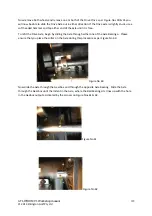
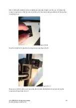
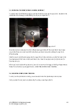
Figure


No


78


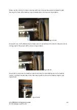
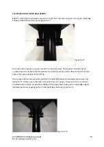
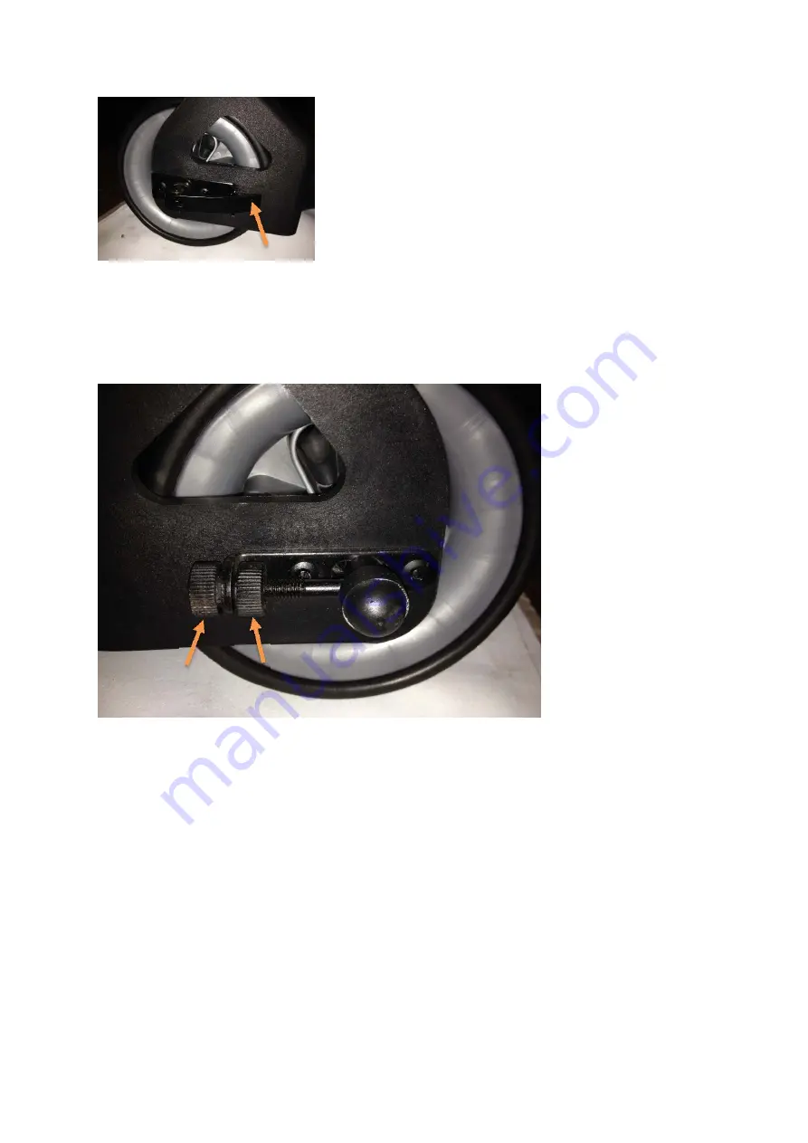
Now


adjust


the


thumb


wheels


as


indicated


by


arrows,


as


per


Figure


No


79.


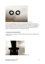
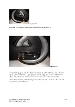
Figure


No


79


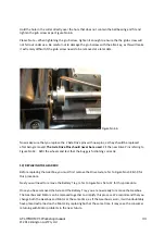
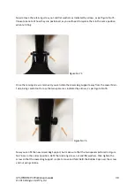
To


make


the


buggy


go


more


to


the


Left


(when


standing


holding


th


handle)


Lengthen


the


threaded


Adjusting


Rod


and


Shorten


the


Adjusting


Rod,


to


make


the


buggy


go


more


to


the


Right.


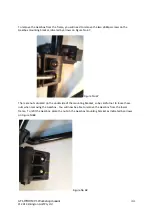
Once


an


adjustment


has


been


made,


the


Cam


Lock


Lever,


must


be


put


back


in


the


locked


position.


After


each


adjustment,


check


the


tracking


on


a


flat


surface


and


make


sure


that


the


Thunb


Wheels


are


tightened


against


each


other.


Summary of Contents for GT LITHIUM V1

Page 1: ...GTLITHIUMV1Workshopmanual 1 2013 Elkington Golf Pty Ltd GT LITHIUM V1 Workshop manual For Approved E L K Golf Service Centres...

Page 2: ...CONTROLLER Page 13 16 6 REPLACING THE MOTOR Page 16 18 7 REPLACING THE AXLE DRIVE PINS Page 19 8 REPLACING THE STEM CABLE Page 20 26 9 REPLACING THE AXLE BEARINGS Page 26 28 10 REPLACING REMOVAL OF T...

Page 3: ...the handle and Upper main frame tube Ensure they are in place before refitting the handle Refer to Figure No 15A Figure No 1 2 REPLACING THE SPEED CONTROL SWITCH With the top handle assembly removed...

Page 4: ...tem Cable Wiring from the Terminal Block as pictured in Figure No 3 PLEASE NOTE The Stem Cable Wiring is colour coded and the colour of each wire must correspond with the colours printed on the Termin...

Page 5: ...wdriver in the position as pictured in Figure No 5 and gently shift the speed dial in the direction of the arrows shown as far as you can to the right by rotating the screwdriver PLEASE NOTE Be extrem...

Page 6: ...ecially supplied Spanner which was supplied to you with your Service Centre Start Up Kit as pictured in Figure No 7 PLEASE NOTE While loosening the securing nut you will need to slide the Speed Switch...

Page 7: ...gure No 7 Once the Speed Switch securing nut has been completely loosened keep sliding the Speed Switch in the direction of the arrow as pictured in Figure No 7A until it is completely free from the T...

Page 8: ...on the housing of the switch as pictured in Figure No 9 The locating lug on the switch needs to be positioned correctly into the Top Handle Assembly as pictured and defined in the section of the Top...

Page 9: ...assembly defined by an arrow Figure No 10 Once the Speed Switch is placed into the top handle as previously shown in Figure No 9 the Speed Dial must be placed onto the shaft of the Speed Switch aligni...

Page 10: ...d force the nut on with a spanner and cross thread the nut PLEASE NOTE It is extremely important to ensure the Locating Lug on the Speed Switch is located correctly into the slot on the Top Handle ass...

Page 11: ...with the colour printed on the terminal block Fit the Stem Cable securing bracket and refit the handle to the buggy by referring to paragraph No 4 Test the operation of the speed switch and ensure th...

Page 12: ...le please ensure that the 3 bushes sleeves are in place on some models only as indicated by arrows on Figure No 15A Please be careful not to drop these bushes into the main upper frame tube when refit...

Page 13: ...Lithium Motor Controller is rubber mounted and the rubber mountings that are positioned on the mounting screws of the Motor Controller MUST be put back in place when replacing the unit To remove the...

Page 14: ...Golf Pty Ltd Loosen Screws enough to free Motor Controller form the battery tray but do not remove the screws completely as the rubber bushes will fall off the retaining screws Refer to Figures No 18...

Page 15: ...Figure no 21 The Motor Controller is now free to be removed Make sure that you do not loose any rubber bushes in the process Figure No 21 To fit the new Motor Controller start by refiting the Battery...

Page 16: ...that all 4 screws are started correctly and not cross threaded before tightening completely Once all 4 srews are tight re connect the Stem Cable Wiring and Motor wiring then fit 3 new cable ties and s...

Page 17: ...is correctly positioned on the flange of the Gearbox It is adviseable to use either silicone or grease to help keep this seal in place prior to fitting the new Motor as per Figure No 27 Figure No 27 E...

Page 18: ...g screws and ensure that the Motor is correctly seated against the Gearbox flange by holding inward pressure on the Motor and then tighten the 3 screws evenly Refer to Figure No 29 Figure No 29 Re con...

Page 19: ...g the Red wheel release tab on the wheel as per figure No 30 To remove the old Drive pin use a 4mm punch as pictured in Figure No 31 To install new Drive pin use a small hammer and gently tap the pin...

Page 20: ...sed within a flexible protective tube as shown in Figure No 33 Figure No 33 Keep pulling outward on the flexible tube in the direction of the arrow until the Stem Cable is released from the upper sect...

Page 21: ...rection of the arrow until it is completely free from the Main Tube Refer to Figure No 36 Figure No 36 Once the Stem Cable has been removed from the Lower Main tube you will see a large rubber grommet...

Page 22: ...ame where the Stem Cable exits in the lower section of the frame and now you can fully remove the Stem Cable for replacement Refer to Figure No 38 Figure No 38 Now you can begin to fit the new Stem Ca...

Page 23: ...of the frame in the direction of the arrow and make sure the small rubber grommet is fitted into the frame first Refer to Figure No 41 Figure No 41 Please ensure that the wiring exits the lower secti...

Page 24: ...he Stem Cable and refit the grommet back into the lower frame section as per Figure No 44 Figure No 44 Now begin to feed the Stem Cable into the lower Main Tube as per Figure no 45 Figure No 45 Feed t...

Page 25: ...Cable as per Figure No 47 and as mentioned earlier fit this flexible cover back in the position that it originally was Figure No 47 Now feed the Stem Cable into the upper Main Tube all the way and ens...

Page 26: ...itted as per paragraph No 4 9 REPLACING THE AXLE BEARINGS To Replace either the left or right axle bearings you will first have to remove either one or both of the wheels and the Axle Drive Pins Refer...

Page 27: ...visible and it should push out of the housing quite easily but if required it may need a light tap with a small hammer and punch To fit the new Bearing simply push the bearing into the housing and you...

Page 28: ...BATTERY TRAY To remove or replace the Battery Tray you will need to turn the buggy upside down First you will have to remove the cable ties securing the wiring to the lower frame Now unplug and disco...

Page 29: ...6 Once the 4 mounting brakets that secure the Battery Tray are removed the Battery Tray can now be removed from the lower frame complete with the Motor Controller as per Figure No 57 Figure No 57 To r...

Page 30: ...ollar and rotate the axle 180 degrees you will be able to see a small ball bearing on the ouput shaft that secures the Drive Axle to the Gearbox output shaft indicated by an arrow as per Figure No 59...

Page 31: ...xle until it is free To refit the Drive Axle begin by sliding the Axle through either one of the Axle Bearings Please ensure that you place the collar on the Axle during this procedure as per Figure N...

Page 32: ...per Figure No 63 Figure No 63 Now push nown on the Ball Bearing and make sure it is seated fully in the Indent in the axle and not sitting proud of the output shaft as shown in Figure No 64 Figure No...

Page 33: ...e Drive Pins should never be re used Fit the new Drive Pins refering to Figure No 32 Refit the wheels and test that the buggy is fuctioning correctly 12 REPLACING THE GEARBOX Before replacing the Gear...

Page 34: ...racket idicated by arrows on Figure No 67 Figure No 67 There are nuts situated on the underside of the mounting bracket so be careful not to loose these nuts when removing the Gearbox You will now be...

Page 35: ...d by arrows on Figure 69 so that the nuts do not fall out of the bracket during installation of the Gearbox mounting screws Figure No 69 Now fit and tighten the Gearbox monting screws as per Figure No...

Page 36: ...and retaining nut please take note of where the flat washers and retaining nut are used as they will need to be put back in the same positions when refiting Now remove the two sleeves which position t...

Page 37: ...two caps which cover the retaining screw and nut please ensure that silicone is used to secure the caps Please Note That when fitting the two sleeves and spacers back into the Upper Main Tube that yo...

Page 38: ...screw is removed you can slide the Lower Bag Support away from the Lower Main Tube being careful not to lose the two spacers as indicated by arrows as per Figure No 76 Figure No 76 Now you can fit the...

Page 39: ...Main Tube before fitting the new Front Wheel Housing Slide the new Front Wheel Housing onto the Lower Main Tube and make sure that the holes in the housing align with the holes in the Lower Main Tube...

Page 40: ...more to the Left when standing holding th handle Lengthen the threaded Adjusting Rod and Shorten the Adjusting Rod to make the buggy go more to the Right Once an adjustment has been made the Cam Lock...

Reviews: