CHAPTER 1. AIRCRAFT MODULES
1.7. KING AIR B200
change required to maintain the chosen vertical speed. If the VS button is not used then the command bars
will simply direct the pilot to maintain the selected pitch attitude. Electric trim may be utilized during this
mode.
To operate in basic autopilot mode, simply press the AP ENG button on the avionics panel. This
activates the Yaw Damper (YD) and Autopilot (AP) which by itself is the most basic functional mode. In
this mode you may depress and hold the Control Wheel Steering (CWS) button on the left side of the yoke to
make pitch and heading changes. When the CWS button is released the aircraft will hold the current heading
and maintain the current pitch attitude. This is not necessarily an altitude hold feature. The command bars
will not be present during this type of operation. During this operation the control knob may also be used
to make pitch and heading changes, however, the control knob will only select a rate of vertical speed and/or
bank angle. The resultant amount of vertical speed and bank angle is dependent upon the degree of knob
deection. The rocker switch on the autopilot portion of the AP 4000 may be used in place of the control
knob for vertical speed selection. There is no alternative switch available for the bank angle function. The
mouse must be used for all on-screen control knob use.
To operate in full autopilot mode, press AP ENG and BC. BC couples the autopilot and allows precise
vertical and horizontal ight management. The command bars will only be present HDG, NAV or APR
is selected. To maintain altitude, simply y the aircraft to the desired altitude and press ALT, or, use
the CWS button to pitch the aircraft toward the target altitude, let go of the CWS button, set the target
altitude into the "Set Altitude" vbox and press VS, ALT SEL and BC. Remember that pressing the CWS
button will disengage the autopilot coupling. Another method is to use the vertical speed rocker switch on
the AP 4000 to initiate a climb or descent. This rocker switch does not disengage the coupling, but the VS
and ALT SEL buttons will need to be pressed to cause the aircraft to level-o at the "Set Altitude" value.
Using the VS function in a climb or descent will cause the aircraft to pitch as necessary to maintain the
desired vertical speed should throttle and/or conguration changes occur. If the VS function is not used
then the aircraft will maintain the original pitch attitude causing the vertical speed and airspeed indications
to change as necessary. To maintain a heading, simply move the heading bug to the desired heading value
and press HDG. The aircraft will turn the shortest distance to the bug position. To change heading simply
move the heading bug to a new value. To track a VOR radial, select the desired course To or From the VOR
with the course deviation needle. Use the heading function to setup the desired intercept angle and then
press NAV. The aircraft will intercept and track the course if the intercept angle is less than, or equal to,
90
◦
in NAV mode for both VOR radials and LOC courses. To track a LOC using APR mode, use the same
procedure as that for a VOR radial intercept. Maximum angle of intercept for a LOC in APR mode is
89
◦
.
The glideslope capture only works when using APR mode, however NAV mode will track a LOC course.
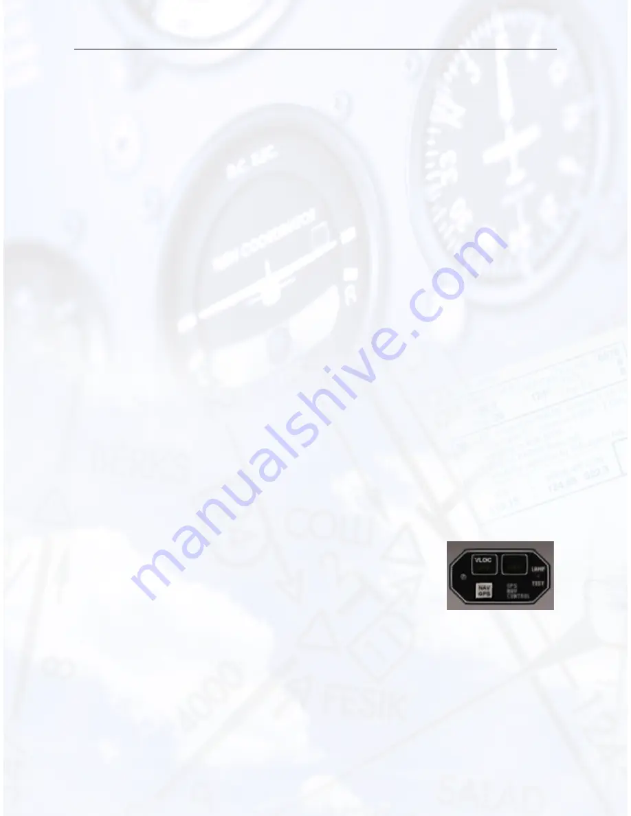
GPS-NAV Control
GPS navigation using the autopilot may be accom-
plished by rst selecting the desired navigational x on
the GPS, then pressing the NAV GPS button on the
GPS-NAV CONTROL box located above the Attitude
Indicator and then pressing NAV on the autopilot.
The 1/2 BK function should be used when to avoid excessive banking during tracking operations, especially
when close to a VOR.
The autopilot automatically utilizes this function once established on a LOC course in both NAV and APR
modes, although the 1/2 BK button will then not be illuminated.
58
Summary of Contents for XTS
Page 4: ...CONTENTS CONTENTS 2 Conclusion 84 2 1 Troubleshooting 84 2 2 Notes 85 2 ...
Page 18: ...CHAPTER 1 AIRCRAFT MODULES 1 2 PIPER ARROW Figure 1 13 Gear up Climb Performance 16 ...
Page 28: ...CHAPTER 1 AIRCRAFT MODULES 1 3 BEECH BARON 58 Figure 1 22 Beech Baron 58 Climb 26 ...
Page 30: ...CHAPTER 1 AIRCRAFT MODULES 1 3 BEECH BARON 58 Figure 1 24 Beech Baron 58 Cruise Power 28 ...
Page 34: ...CHAPTER 1 AIRCRAFT MODULES 1 4 BONANZA A36 Figure 1 30 Bonanza A36 Instrument Panel 32 ...
Page 39: ...CHAPTER 1 AIRCRAFT MODULES 1 4 BONANZA A36 Figure 1 32 Bonanza A36 Climb 37 ...
Page 41: ...CHAPTER 1 AIRCRAFT MODULES 1 4 BONANZA A36 Figure 1 34 Bonanza A36 Cruise Power Settings 39 ...
Page 54: ...CHAPTER 1 AIRCRAFT MODULES 1 6 CESSNA 182S 52 ...
Page 55: ...CHAPTER 1 AIRCRAFT MODULES 1 6 CESSNA 182S 53 ...
Page 56: ...CHAPTER 1 AIRCRAFT MODULES 1 6 CESSNA 182S 54 ...
Page 73: ...CHAPTER 1 AIRCRAFT MODULES 1 8 MOONEY M20J Figure 1 56 Mooney M20J Instrument Panel 71 ...
Page 76: ...CHAPTER 1 AIRCRAFT MODULES 1 9 PIPER SENECA III 74 ...
Page 83: ...CHAPTER 1 AIRCRAFT MODULES 1 9 PIPER SENECA III Figure 1 63 Piper Seneca Speed Power 81 ...
Page 84: ...CHAPTER 1 AIRCRAFT MODULES 1 9 PIPER SENECA III Figure 1 64 Piper Seneca Table 82 ...
Page 87: ...CHAPTER 2 CONCLUSION 2 2 NOTES 2 2 Notes Please feel free to add any notes here 85 ...
Page 88: ......


