background image

9

EVBS-26

machine from power, and switch any two of the three 
leads in the motor junction box  (see section 19.0, 

Wiring 

Diagram

).

9.0  CONTROLS

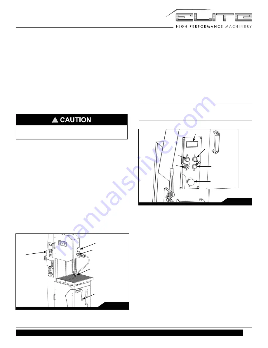
Refer to Figures 2 and 3. 

Low/High Range Shift Lever (B, Figure 2) - 

Pull toward the front of the machine to shift into the low 
speed range. Push toward the rear of the machine to shift 
into the high speed range.

Upper Blade Guide Lock Knob (D, Figure 2) - 

Turn counterclockwise to loosen and clockwise to tighten.

Upper Blade Guide Knob (E, Figure 2) - 

Turn clockwise to raise blade guide assembly; counter-
clockwise to lower.

Work Lamp Switch (F, Figure 2) - 

Located on top of lamp shade; turns lamp on and off.

Shear Lever (G, Figure 2) - 

UP position allows insertion of blade end into shear. Pull 
lever DOWN to cut blade. 

Main Motor Start Switch (H, Figure 3) - 

Press to start band saw.

Main Motor Stop Switch (I, Figure 3) - 

Press to stop band saw. 


!

Do not turn knob while machine is stopped. Adjust 
speed only when machine is running. 

Grinder Toggle Switch (N, Figure 4) - 

Located on blade welder panel. Flip switch up to start 
grinder; fl ip down to stop grinder. 

Weld Button (O, Figure 4) - 

Located on blade welder panel. Press and hold to start 
welding. Shuts off automatically when weld is done. Re-
lease when weld is completed. 

Anneal Button (P, Figure 4) - 

Located on blade welder panel. Press and hold to anneal 
blade, release to stop. 

Blade Clamp Pressure Knob (Q, Figure 4) - 

Located on blade welder panel. Sets pressure for different 
width blades.

Blade Clamps (R, Figure 4) - 

Located on blade welder panel. DOWN position allows 
insertion of blade into clamp. Up position locks blade.

Key Lock Switch (J, Figure 3) - 

Turn to 12 o’clock position and remove key to lock out 
power from the control panel. Insert key and turn to 3 
o’clock position to turn on power to control panel.

Emergency Stop Switch (K, Figure 3) - 

Press to stop all machine functions. Turn 90° to reset.

Power Lamp (L, Figure 3) - 

Illuminated when power is being supplied to band saw.

Digital Readout (M, Figure 3) - 

Indicates blade speed in feet per minute. 

Note: After saw is fi rst started or the speed has been 
changed, allow at least a minute for the readout to 
stabilize the new setting.

Fig. 3

H

I

K

L

J

M

Fig. 2

B

E

D

G

F

Summary of Contents for EVBS-26

Page 1: ...rating Instructions and Parts Manual Vertical Band Saw Model EVBS 26 JET 427 New Sanford Road LaVergne Tennessee 37086 www jettools com Ph 855 336 4032 Part No M 891115 REV B2 02 2017 Copyright 2017 J...

Page 2: ...defects in workmanship or materials subject to the limitations stated below This warranty does not cover failures due directly or indirectly to misuse abuse negligence or accidents normal wear and te...

Page 3: ...EATH INJURIES TO PERSONS OR PROPERTY OR FOR INCIDENTAL CONTINGENT SPECIAL OR CONSEQUENTIAL DAMAGES ARISING FROM THE USE OF OUR PRODUCTS SOME STATES DO NOT ALLOW THE EXCLUSION OR LIMITATION OF INCIDENT...

Page 4: ...13 11 5 KERF 13 11 6 WIDTH 13 11 7 BLADE BREAKAGE 13 12 0 WELDER OPERATION 13 12 1 SHEARING 13 12 2 REMOVING TEETH 14 12 3 WELDING 14 12 4 ANNEALING 15 12 4 1 CARBON STEEL BLADES 16 12 4 2 CARBON STEE...

Page 5: ...oid contact with coolant especially guarding your eyes 17 Always keeps hands and fingers away from the blade when the machine is running 18 Never hand hold the material Always use the vise and clamp i...

Page 6: ...topped Familiarize yourself with the following safety notices used in this manual 4 0 INTRODUCTION This manual is provided by JET covering the safe operation and maintenance procedures for a JET Model...

Page 7: ...ble Size LxW in 27 1 2x23 1 2 Table Height in 39 3 8 Table Tilt 10 L 45 R Overall Dimensions LxWxH in 51x32x83 1 2 Net Weight lbs 1 433 Gross Weight lbs 1 655 The specifications in this manual were cu...

Page 8: ...ew Tighten screw and recheck for level 6 Adjust with additional shims as required until table is level when all mounting screws or nuts are tight 8 0 ELECTRICAL CONNECTIONS The Vertical Band Saw is ra...

Page 9: ...cated on blade welder panel Flip switch up to start grinder flip down to stop grinder Weld Button O Figure 4 Located on blade welder panel Press and hold to start welding Shuts off automatically when...

Page 10: ...res sure method Blade Tension Handwheel S Figure 5 Located on underside of upper frame Turn clockwise to tension blade counterclockwise to release tension on blade Blade Tracking Knob T Figure 5 Locat...

Page 11: ...w wear after continual use Readjust as necessary If the blade guides become difficult to adjust switch the left and right blade guides Blade guides must be properly adjusted or damage may occur to bla...

Page 12: ...tension knob Rotate wheel by hand and make sure blade is properly seated in blade guides Blade guides will have to be adjusted if the replacement blade is a different type and width 10 Turn on saw and...

Page 13: ...larger gullet and are used on softer non ferrous materials such as alumi num copper magnesium and soft brass Hook Tooth provides a chip breaker and has less tendency to gum up in softer materials Used...

Page 14: ...used to cut blade grind ends square as shown Fig 13 Fig 11 12 3 WELDING 1 Clean welder jaws and lower jaw inserts 2 Carefully clean ends of blade which will contact welder jaws Remove any dirt oil sc...

Page 15: ...d clamp jaws during welding 12 4 ANNEALING The blade must now be annealed or cooled at a controlled rate to prevent it becoming too brittle The general procedure follows Specific procedure will depend...

Page 16: ...to comply may cause serious injury Always heed the indicator light when glowing it warns that the grinder motor is running 12 4 3 BI METAL BLADES 1 Heat blade slowly by jogging the annealing switch bu...

Page 17: ...cut then feed rate is excessive If chips are slightly curled and not colored by heat then the blade is sufficiently sharp and is cutting at its most efficient rate Bad Grindings Fig 18 12 6 SECONDARY...

Page 18: ...tables after each day s use 14 1 LUBRICATION SCHEDULE Upper Blade Guide Shaft lightly grease weekly Clean after each day s use Speed Change Handle grease monthly with a light film on teeth and thread...

Page 19: ...wheel alignment Blade quickly becomes dull Blade speed too fast Use slower speed Wrong blade for the job Use proper blade for workpiece Feed rate excessive Decrease feed rate Blade warps Dull blade Sh...

Page 20: ...the full load amps on the motor as noted on the motor plate If amp setting is correct then there is probably a loose electrical lead Building circuit breaker trips or fuse blows Verify that band saw...

Page 21: ...jaws Align ends properly before clamping Worn clamp jaws Replace clamp jaws Clamp jaws not aligned correctly Align jaws correctly Misaligned weld Blade ends are over lapped Pressure knob is set for wi...

Page 22: ...knob accord ingly Jaw movement too slow Put some oil on rear side of welding lever and the two jaws Blade cannot be tightly clamped with the clamp jaws Clamp jaws are out of order or de cayed Replace...

Page 23: ...3 3004 1500 1500 1500 1385 1220 18 10 6 3 3 2024 5052 1500 1500 1500 1500 610 18 10 6 3 3 Magnesium bronze 125 75 40 25 20 14 8 6 3 3 Leaded commercial bronze 915 610 450 305 150 14 8 6 3 3 Commercial...

Page 24: ...service department call 1 855 336 4032 Monday through Friday see our website for business hours www jettools com Having the Model Number and Serial Number of your machine available when you call will...

Page 25: ...25 EVBS 26 BREAKDOWN ASSEMBLY EVBS 26...

Page 26: ...ed Changing Lever 1 22 EVBS20 0740 Shaft Housing 1 23 EVBS20 0790 Speed Lever Right 1 24 EVBS20 7071 Pulley 1 25 EVBS20 9221 Lever Knob 1 26 VB 44 V Belt 7071 7300 60hz A44 2 27 BB 6008 Ball Bearing 6...

Page 27: ...ll Bearing 6201ZZ 1 66 EVBS26 2000 Main Drive Motor 3HP 230 460V 3PH 1 67 EVBS26 2011 Motor Pulley 1 68 VB 43 V Belt 2011 7070 A43 2 69 VB 60 V Belt 2011 4450 A60 1 70 EVBS26 3010 Lower Wheel 1 71 EVB...

Page 28: ...20 9591 Handle Arm 2 113 EVBS20 9600 Chip Stopper 1 114 EVBS20 9700 Indicate Middle 1 115 EVBS20 9780 Brusher Bracket 1 116 EVBS20 9790 Chip Brusher 1 117 EVBS20 9850 Key Of Rear Door 1 118 EVBS26 988...

Page 29: ...7110 Worm 1 155 EVBS26 7120 Whirling Arm 1 156 EVBS26 7200 Spring Housing 1 157 EVBS26 7210 Spring 1 158 EVBS26 7220 Variation Disk Lower Outer 1 159 EVBS26 7230A Variation Disk Lower Inner 1 160 EVBS...

Page 30: ...187 168 170 142 165 164 166 167 171 149 150 148 199 198 195 196 173 193 192 197 194 191 194 190 190 193 178 179 177 176 175 174 181 182 145 172 147 156 154 146 151 187 158 152 151 157 155 153 158 159...

Page 31: ...159 EVBS20 EV 6130 Moving Jaw 1 160 EVBS20 615 Weld Button 1 161 EVBS20 HV 6160 Micro Switch 1 162 EVBS20 EV 6161 Switch Bracket 1 163 EVBS20 EV 6170 Pressure Adjust Knob 1 164 EVBS20 EV 6180 Shaft 1...

Page 32: ...10V 12V 20W 1 190 EVBS20 EV 1910 Spindle Bushing 3 191 EVBS20 EV 1920 Spindle Lift 1 192 EVBS20 EV 1930 Blade Shaft 1 193 EVBS20 EV 1940 Vaned Iron Plate 2 194 EVBS20 EV 1950 Lower Blade 2 195 EVBS20...

Page 33: ...L12 22 43 22 42 34 32 22 31 29 29 27 27 26 L3 L2 L1 9 1 5 3 2 4 7 6 8 11 10 12 9 1 5 3 2 4 7 6 8 11 10 12 TB1 TB2 3 1 2 12 4 5 6 7 10 9 8 11 TB3 18 17 16 15 14 13 12 L32 10 W V U 6 5 4 3 2 1 L12 22 4...

Page 34: ...30V 230V 230V 10 L32 12 13 14 15 16 17 18 22 FU6 24 4A 2 1 25MM SB1 SB2 SQ3 1 2 3 4 5 3 4 5 6 7 8 4 2KVA 150W TB3 10 11 3 2 25KW 60HZ 3 60HZ M1 3 9 26 TB2 TB2 TB2 TB2 TB2 TB2 TB2 TB3 TB3 TB3 TB3 TB3 T...

Page 35: ...V TB1 10 31 SA4 30 SB3 HL FR 34 KM1 26 TB1 8 7 29 TB1 6 5 27 27 SQ2 TB1 SQ1 TB1 32 KM1 SB5 11 TB1 110V 26 TB1 4 9 TB1 31 SB4 SB1 SB2 SB3 SB4 SB5 SA1 SA2 WELD ON ANNEAL ON EMERGENCY STOP MAIN MOTOR OFF...

Page 36: ...36 Vertical Band Saw NOTES...

Reviews: