background image

11

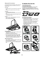
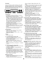
Control and features 


This hood is equipped with an electronic motor and lamp 

control. The control is able to set 3 different fan speeds, turn 

ON/OFF light and has a timer function. In the following draw-

ing are described the main key functions. 


1. Timer Key

The default timer setting is 10 minutes, and it can be 


adjusted between 20 minutes and 1 minute.

After pressing the timer key, the control enters to a timer 


setup mode, and user can adjust the timer countdown 


time with the “-” and “+” keys within 5 seconds. The timer


can be initiated immediately pressing the timer key, after 


setting the timer duration or pressing the timer key twice 


(default 10 minutes setting).

If not action occurs within 5 seconds the countdown will start.

During the timer setup the “-” and “+” keys are dedicated


to the timer and no motor action will occur.

Once initiated the timer, it can be cancelled by pressing 


the timer key again. 

. Light Key

Press lamp key to turn ON the light (Lamp state previously OFF).

Press lamp key to turn OFF the light (Lamp state previously ON).


3. Display

Shows the hood settings. 

4. “-” Key. Speed Decrease / OFF

This key is used to decrease the fan speed, or turn OFF 


the fan.

The fan will turn OFF if the “-” key is pressed and the


hood was in the first speed.

If the fan is at second speed and the “-” key is pressed,


the fan will be set to first speed.

If the fan is at third speed and the “-” key is pressed, the


fan will be set to second speed.

If the fan is OFF and the “-” key is pressed, the control


backlight will light up.


5. “+” Key. Speed Increase / ON

This key is used to increase the fan speed, or turn  


ON the fan.

The fan will turn ON if the “+” key is pressed and the 


hood was OFF.

If the fan is at first speed and the “+” key is pressed, 


the fan will be set to second speed.

If the fan is at second speed and the “+” key is pressed,  


the fan will be set to third speed.

If the fan is at third speed and the “+” key is pressed, 


a beep will sound.


Special functions


Clock programming

The clock can be reprogrammed at any time except  


during an active timed function. 


1 2 3


The clock can be displayed in a twelve hour format and 


valid clock times are from 1:00 to 12:59.

The clock can be reprogrammed pressing the “Timer”


key for 5 seconds, and after, the clock can be adjusted 


with the “+” and “-” keys. Colon “:” will flash indicating


clock programming mode.

The user can have minute increments / decrements of 1 


minute, but if the user keep pressing the “+”/”-” keys


for more than 1 second, the increments / decrements will 


be of 5 minutes. During this option the control will 


round to the nearest 5 minutes.

The user can finish on reprogramming the clock pressing


the “timer” key.

After 1 minute of no key pressed the control will accept 


the programmed clock time and will add one minute 


to the set clock. 

Grease filter saturation alarm

After thirty fan functional hours, the display will show   


“Grease Filter” if the fan is active. When this icon is


shown in the display, the grease filters installed are 


required to be washed.

To reset the grease filter saturation alarm the user must


press the “+” key for 5 seconds, after this action the


icon “grease filter” is not display, and the hood has the


normal display operation. 

Charcoal filter saturation alarm (Recirculating accessories)

After one hundred and twenty functional hours of the fan, 


the display will show “Charcoal Filter” if the fan is active.


When this icon flashes on display, the charcoal filters


installed are required to be replaced or reactivated.

To reset the grease filter saturation indication the user


must press the “-” key for 5 seconds, after this time


the icon “charcoal filter” is not display and the hood has


the normal display operation. 

Audible signal activation and deactivation

The audible signals can be activated or deactivated 


pressing the “Light” key for 5 seconds.

If the audible signal is activated, a tone must sound and 


the “Snd” symbol must appear on the display for 2 second.

If the audible signal is deactivated, the “Snd” symbol must


appear on the display for 2 second and no sound must sound.

Charcoal filter inclusion and exclusion 


(Recirculating accessories)

The charcoal filter inclusion or exclusion can be set by


pressing the “-” and “+” keys at the same time for 5 seconds.

The Inclusion or exclusion of charcoal filter must be 


selected while the lamps and the motor are OFF.

When the charcoal has been excluded, the charcoal filter


alarm is disabled. 

Heat sensor

The control is equipped with a heat sensor that will turn 


on the blower at second speed if excessive heat 


occurs (over 70°C) surrounding the control area.

If the blower is OFF or if it is operating at first speed, the


blower will be set automatically to second speed.

During this state, the user may raise the blower speed to 


third speed but can not decrease the speed.

When the temperature level on the hood drops to normal, 


the blower will operate in the setting defined by the user


before the alarm occured.

Summary of Contents for ETB436SS

Page 1: ...Installation Guide Guide d utilisation d entretien et d installation Guía de instalación uso y mantenimiento READ AND SAVE THESE INSTRUCTIONS LISEZ CES INSTRUCTIONS ET CONSERVEZ LES LEA Y GUARDE ESTAS INSTRUCCIONES ...

Page 2: ...ts Important safety Notice 3 Electrical Installation requirements 4 Electrical requirements 4 Before installing the hood 4 List of Materials 5 Parts supplied 5 Parts not supplied 5 Installation Requirements 5 Before Installing the hood 5 Product Dimensions Clearances 5 Installation preparation 6 Installation Instructions 7 Ductwork and wiring locations 6 Duct Fittings 7 Ceiling ducting 8 Wall duct...

Page 3: ...RNING To Reduce The Risk Of Fire Or Electric Shock Do Not Use This Hood With Any External Solid State Speed Control Device WARNING TO REDUCE THE RISK OF A RANGE TOP GREASE FIRE Never leave surface units unattended at high settings Boilovers cause smoking and greasy spillovers that may ignite Heat oils slowly on low or medium settings Always turn hood ON when cooking at high heat or when flambeing ...

Page 4: ...it breaker box through metal electrical conduit Wire sizes must conform to the requirements of the National Electrical Code ANSI NFPA 70 latest edition or CSA Standards C22 1 94 Canadian Electrical Code Part 1 and C22 2 No 0 M91 latest edition and all local codes and ordinances A U L or C S A listed conduit connector must be provided at each end of the power supply conduit at the range hood and at...

Page 5: ... installing the hood For the most efficient air flow exhaust use a straight run or as few elbows as possible CAUTION Vent unit to outside of building only At least two people are needed for installation On average one to three hours are necessary to complete installation without considering cut to be done on wall and or on cabinet installation ducts conduit and electrical connections to the mains ...

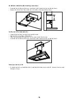
Page 6: ...izontal support The vent hood should be on site before final framing and wall finishing This will help to accurately locate the duct work and electrical service Installation will be easier if the vent hood is installed before the cook top and countertop are installed Removing the packaging CAUTION Remove the carton carefully Wear gloves to protect against sharp edges WARNING Remove the protective ...

Page 7: ...ft 3 1 4 x 12 to 8 round transition 90 elbow 17 ft 8 round wall cap with damper 30 ft 3 1 4 x 12 wall cap with damper 30 ft 8 round roof cap 26 ft 8 round roof vent 26 ft DUCT FITTINGS Use this chart to compute maximum permissible lengths for ducts runs to outdoors NOTE Do not exceed maximum permissible equivalents lengths Flexible ducting If flexible metal ducting is used all the equivalent feet ...

Page 8: ...he ceiling Use level to draw a line straight up from the centerline on the template to the ceiling Measure at least 4 12 16 from the back wall to the circle center of an 8 hole on the ceiling Wall ducting If ductwork will vent to rear Use a level to draw a line straight up from the centerline on the template Measure at least 23 12 16 the measure might vary dependig on the elbow used above the penc...

Page 9: ...uctwork Install ductwork making connections in the direction of airflow as illustrated Push duct over the exhaust outlet Wrap all duct joints and the flange connections with duct tape for an airtight seal Make the same connection in the wall or ceiling vent exit Making the electrical connections WARNING ELECTRICAL SHOCK HAZARD TURN OFF POWER CIRCUIT AT THE SERVICE PANEL BEFORE WIRING THIS UNIT 120...

Page 10: ...upper part of the telescopic duct cover pull it and place it in the duct cover mounting bracket House Wiring UL listed nuts Metal Electrical Conduit Secure the top of the duct with 2 assembly screws provided Secure the bottom of the duct with 2 assembly screws provided Use Care Instructions Before using your hood read this manual carefully The infor mation on the following pages will help you oper...

Page 11: ...nts decrements of 1 minute but if the user keep pressing the keys for more than 1 second the increments decrements will be of 5 minutes During this option the control will round to the nearest 5 minutes The user can finish on reprogramming the clock pressing the timer key After 1 minute of no key pressed the control will accept the programmed clock time and will add one minute to the set clock Gre...

Page 12: ...n the direction of the grain Follow the cleaner instructions for cleaning the stainless steel surface Lamp bulb maintenance Use a Phillips 2 screw driver to remove the lamp cover Remove it carefully from its housing Remove the damaged lamp bulb turn counter clockwise and replace it with a new bulb E12 Philips Lamp 120V 40W Available Accesories Charcoal filter placement Recirculating accessories Fi...

Page 13: ...he measured size Uninstall the air deflector removing the 4 assembly screws Slip the duct onto the bottom of the deflector Place the assembled deflector and duct over the exhaust outlet from the hood Assemble the air deflector with the duct cover bracket with 4 assembly screws provided as shown Telescopic duct cover Kit For telescopic duct cover installation refer to Installation Instructions sect...

Page 14: ...y from the hood 3 Verify that the connector coming from the motor is well connected to the connector mounted in the plastic and that the locking system in the connectors is well locked 4 If the connectors are not well connected Hold and press main connectors attached in the white plastic Push inwards the motor lamp connectors until the locking system on connectors is well attached 5 Connect hood t...

Page 15: ...to operator abuse improper maintenance use of corrosive or abrasive cleaning products pads and oven cleaner products WHO IS COVERED This warranty is extended to the original purchaser for products purchased for ordinary residential use in North America Including the United States Guam Puerto Rico US Virgin Islands Canada This warranty is non transferable and applies only to the original purchaser ...

Page 16: ...ircuit de dérivation de 15 V c a 20 Hz de 15 ou 20 A Français Sommaire Avis de sécurité important 17 Exigences électriques 18 Liste de Piéces 19 Pièces fournies 19 Pièces no fournies 19 Exigences de l Installation 19 Avant d installer la hotte 19 Dimensions et Dégagement 19 Préparation de l installation 20 Installation 20 Endroits conduits et de câblage 20 Mesures Conduits 21 Conduits sur le plafo...

Page 17: ...un contrôleur de vitesse à semi conducteurs AVERTISSEMENT POUR RÉDUIRE LES RISQUES D INCENDIE DE GRAISSE SUR LES CUISINIÈRES A B C D E F Ne laissez jamais la cuisinière sans surveillance lorsqu elle est réglée à une haute température Les débordements par bouillonnement causent de la fumée et des débordements de gras qui peuvent s enflammer Faites chauffer l huile lentement à une température basse ...

Page 18: ...ans le circuit neutre ou le circuit de mise à la terre IMPORTANT Conservez ces instructions afin de pouvoir les remettre à l inspecteur électricien La hotte doit être câblée uniquement à l aide de fils de cuivre Il faut raccorder la hotte directement à une boîte à fusible ou à un disjoncteur par l entremise d une canalisation électrique en métal Le calibre de fil doit être conforme aux exigences d...

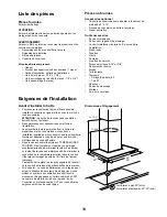
Page 19: ... plus efficace possible installez la conduite en ligne droite ou avec le moins de coudes possibles ATTENTION La sortie de la conduite de ventilation doit donner sur l extérieur Deux personnes sont nécessaires pour effectuer l installation La quincaillerie fournie permet de fixer la hotte à la plupart des murs et des plafonds consultez un installateur qualifié pour vous assurer que la quincaillerie...

Page 20: ...ur sec la hotte doit être sécurisé à montants verticaux dans le mur ou à un support horizontal La hotte doit être sur place avant de cadrage final et mur de finition Cela aidera à localiser avec précision les travaux conduits et de service électrique L installation sera plus facile si la hotte est installée avant que le cuisinier dessus et le comptoir sont installés Retrait de l emballage ATTENTIO...

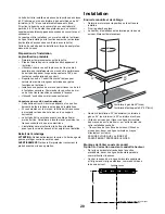
Page 21: ...ral rect registre 30 pi 8 chapeau de toiture circ 26 pi 8 conduit de toiture rond 26 pi Attacher les équerres au mur Aligner les lignes médianes tracées sur les équerres avec les lignes médianes sur le mur Indiquer les 2 trous pour les vis sur le mur Forer des trous pilotes de 5 16 sur les emplacements indiqués Placer les attaches d accrochage au mur Visser les vis à bois à la main dans les attach...

Page 22: ...auche de la hotte Le câblage doit entrer dans le mur arrière d au moins 20 au dessus du bas de la hauteur d installation et au sein 5 7 8 et 4 7 8 du côté gauche de l axe Utiliser pour l installation 1 2 de taille commerciale UL conduit métallique cotées Installez encadrement pour support de la hotte Si placoplâtre est présent marquer l emplacement des trous de vis Retirer le gabarit Coupez le pla...

Page 23: ...s la direction du flux d air comme illustré Pousser le conduit dans la sortie d évacuation Recouvrir tous les joints des conduits et les raccords à la bride avec de la toile isolante pour une fermeture hermétique Effectuer la même opération pour le raccordement à l évacuation dans le mur ou dans le plafond Effectuer les connexions électriques AVERTISSEMENT DANGER DE CHOC ÉLECTRIQUE AVERTISSEMENT C...

Page 24: ... conduit de cheminée Boîte des fils Ecrou métalique liste U L Conduit métalique électrique Assurer le dessus du conduit à l aide des 2 vis d assemblage fournies Assurer le bas du conduit à l aide des 2 vis d assemblage fournies Utilisation et d entretien Instructions Avant d utiliser votre hotte lire attentivement ce manuel Les informations sur les pages suivantes vous aideront à fonction ner et d...

Page 25: ... des boutons Deux points clignotera indiquant le mode 100 d horloge L utilisateur peut avoir des incréments décroissances minutieux de 1 minute mais si le pressurage de subsistance d utilisateur les boutons pour plus de 1 seconde les incréments décroissances auront lieu de 5 minutes Pendant cette option la commande rond aux 5 minutes les plus proches L utilisateur peut finir sur reprogrammer l hor...

Page 26: ...urface dans le sens du grain Suivez le nettoyeur des instruc tions pour le nettoyage de la surface en acier inox Entretien lampe ampoule Utiliser un tournevis Phillips pour retirer la vis du protège ampoule Retirer le protège ampoule et le mettre de côté avec la vis Retirer l ampoule et la remplacer par une ampoule neuve de E12 Philips 120V 40W Accessoires disponibles Placement du filtre au charbo...

Page 27: ...teur d air en retirant les 4 vis d assemblage Glisser le conduit dans le fond du déflecteur Placer le déflecteur et le conduit assemblés sur la sortie d évacuation de la hotte Assembler le déflecteur d air au crochet du conduit d évacuation avec les 4 vis d assemblage fournies comme indiqué sur la figure Kit conduit télescopique couvercle Pour l installation del couverture conduit télescopique rev...

Page 28: ...venant du moteur est bien raccordé au connecteur monté dans le plastique Vérifier que le système de verrouillage dans les connecteurs sont bien verrouillées 4 Si les connecteurs ne sont pas bien connectés Maintenir et appuyer sur les connecteurs principaux attachés dans le plastique blanc Poussez vers l intérieur les connecteurs du moteur de la lampe jusqu à le système de verrouillage sur les conn...

Page 29: ...consommable Usure normale Usure due à une mauvaise utilisation du propriétaire un entretien incorrect une utilisation de substances nettoyantes corrosives ou abrasives et produits de nettoyage pour four QUI EST COUVERT Cette garantie s étend à l acheteur original de produits achetés pour un usage domestique habituel en Amérique du Nord Y compris Etats Unis Guam Porto Rico les Iles virgin Américain...

Page 30: ...es del producto 33 Preparación para la instalación 34 Instrucciones de Instalación 34 Ubicación de los conductos y la instalación eléctrica 34 Dimensiones de los ductos 35 Instalación del conducto hacia el techo 36 Instalación del conducto hacia la pared 36 Instalación del armazón de soporte para la campana 36 Montaje de la campana 37 Conexión del conducto 37 Preparación de las conexiones eléctric...

Page 31: ...ONES PERSONALES TENGA PRESENTE LO SIGUIENTE Utilice esta unidad sólo de la manera indicada por el fabricante Si tiene preguntas póngase en contacto con el fabricante Antes de realizar un mantenimiento o limpieza de la unidad desconecte y bloqueé el panel de servicio para evitar que se conecte accidentalmente Si el panel de servicio no puede ser bloqueado coloque una etiqueta de prevención en el pa...

Page 32: ...campana La campana de cocina debe conectarse directamente a la caja de fusibles o cortacircuitos a través del conducto eléctrico metálico Los tamaños del cable deben ser conforme con los requisitos del Código Eléctrico Nacional ANSI NFPA 70 última edición y todos los códigos locales y estatutos Copias de los estándares listados pueden ser obtenidos en Asociación Nacional de Protección Contra Incen...

Page 33: ...de la corriente de aire más eficiente utilice una línea recta o con pocos codos PRECAUCIÓN Proveer la salida del aire solamente hacia el exterior del edificio Por lo menos dos personas son necesarias para la instalación En promedio se necesitan de dos a tres horas para completar la instalación sin considerar el corte que debe ser llevado a cabo en la pared o gabinete conductos de instalación tubo ...

Page 34: ...izontal en la pared La localización de la campana debe estar decidida antes de terminar con la instalación de soportes o terminados de la pared La instalación será más fácil si se instala la ventilación de la campana antes de instalar la estufa y la superficie de cocina y o fregador área de lavaplatos Retirar el empaque PRECAUCIÓN Retire el cartón con cuidado Utilice siempre guantes especiales con...

Page 35: ...1 4 x 12 con válvula antirretorno 30 ft Casquete de techo redondo de 8 26 ft Respiradero de techo re dondo de 8 26 ft DIMENSIONES DE LOS DUCTOS Use esta tabla para calcular las longitudes máximas ad misibles NOTA no exceder las longitudes máximas permisibles Conductos flexibles si se usan conductos flexibles de metal todos los valores de los pies de la mesa deberían ser dobla dos El conducto flexi...

Page 36: ...ctrico de casa La caja de conexión se encuentra en la parte superior de la campana El cableado deberá entrar en la pared por lo menos de 20 por encima de la altura inferior de la instalación y entre 5 7 8 y 4 7 8 del lado izquierdo de la línea de centro Utilice para la instalación conducto de metal de enlistado por UL Instalación del armazón de soporte para la campana Si se cuenta con pared falsa ...

Page 37: ...onducto haciendo conexiones en dirección a la corriente de aire como se ilustra Empuje el conducto encima de la sálida de escape Selle hermeticámente todas las coyunturas articulaciones de los conductos y las abrazaderas de conexión con cinta para conductos Realice la misma operación para la salida de aire de pared o de techo Preparación de la conexiones eléctricas ADVERTENCIA RIESGO DE DESCARGA E...

Page 38: ...co de metal Coloque la parte superior de la cubierta del conducto Si se usa una cubierta telescópica del conducto tome la parte superior de la cubierta y posiciónela en el soporte de montaje de la cubierta del conducto Sujete la parte superior del conducto con 2 tornillos de montaje 2 provistos Instrucciones para el Uso y el Mantenimiento Antes de utlizarla campana lea cuidadosamente este manu al ...

Page 39: ...ador por 5 segundos y después el reloj puede ser ajustado con las teclas y Colon destellará indicando la modalidad programación del reloj El usuario puede incrementar disminuir los minutos de 1 minuto pero si sigue pulsando las teclas por más de 1 segundo los incrementos disminuciones serán de 5 minutos Durante esta opción el control redondeará a los 5 minutos más cercanos El usuario puede termina...

Page 40: ...o inoxidable o cera Frotar siempre siguiendo la dirección de la veta Siga las instrucciones del limpiador para limpiar la superficie de acero inoxidable Mantenimiento de las lámparas Use un destornillador Phillips 2 para quitar la cubierta de la lámpara Quitar con cuidado Quite la lámpara dañada girar el contador según las agujas del reloj y sustituir con otra lámpara Lámpara E12 Philips 120V 40W ...

Page 41: ...uitando los 4 tornillos de montaje Coloque el deflector montado y la cubierta del conducto por encima de la salida de escape desde la campana Monte el colector de aire con la cubierta del soporte del conducto con 4 tornillos de montaje provistos así como mostrado Use la cinta para conductos para sellar el colector a la salida de escape desde la campana Kit cubierta telescópica del conducto Para la...

Page 42: ...ca 3 Verifique que el enchufe que sale del motor esté bien conectado al enchufe ensamblado en el plástico verificando que el sistema de esclusas en los enchufes esté bien colocado 4 Si los enchufes no están bien conectados Sostenga y mantenga presionados los enchufes principales unidos al plástico blanco 5 Conecte la campana a la corriente eléctrica y verifique El extractor es muy ruidoso Los filt...

Page 43: ...le Desgaste normal Desgaste terminal debido a abusos del usuario mantenimiento inadecuado uso de productos toallas de limpieza corrosivos o abrasivos y por uso de limpiadores para hornos QUIEN ESTA CUBIERTO Esta garantía se extiende al comprador original de productos adquiridos para uso residencial en Norte America incluyendo Estados Unidos Guam Puerto Rico Islas Vírgenes de USA y Canadá Esta gara...

Page 44: ...LI30NA Ed 10 11 Printed in Mexico ...

Reviews: