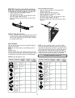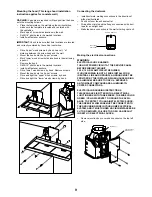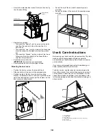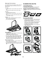
5
List of Materials
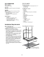
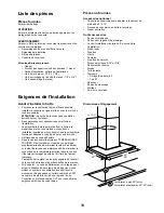
Parts supplied
Removing the packaging
CAUTION!
Remove carton carefully, Wear gloves to protect against
sharp edges.
WARNING!
Remove the protective film covering the product before
putting into operation.
Hood structure assembly with blower, transition.
Lamp already installed.
2 Grease filters 30” or 3 Grease filters 36”.
Duct cover.
Hardware bag with:
Template
Duct cover support bracket (1 piece)
Use, care and installation guide
Wood screws (6 pieces - 3/16” x 1” 3/4)
Concrete wall anchors (6 pieces - 1/8” x 3/8”)
Assembly screws (4 pieces)
•
•
•
•
•
•
•
•
•
•
Parts not supplied
Optional Accessories
Telescopic duct cover to fit ceiling height from 8’ to 10’
Recirculation KIT
Non return valve
Tools/Materials required
Duct tape
Wire nuts
Masking tape
8” rounded metal duct (lenght to suit installation)
Pliers
Gloves
Knife
Safety glasses
Electric drill with 5/16” and 3/8” Bits
Strain relief
Spirit level
Duct tape
Screwdrivers:
Phillips (Posidrive) # 2
Torx #2
Wire cutter/stripper
Hammer
Saw, jig saw or reciprocating saw
•
•
•
•
•
•
•
•
•
•
•
•
•
•
•
•
•
•
•
•
•
Installation Requirements
Before installing the hood
For the most efficient air flow exhaust, use a straight run
or as few elbows as possible.
CAUTION:
Vent unit to outside of building only.
At least two people are needed for installation.
On average one to three hours are necessary to complete
installation (without considering cut to be done on wall
and/or on cabinet, installation ducts, conduit and electrical
connections to the mains).
The hood is fitted with screws and wall anchors suitable
for most surfaces, consult a qualified installer, check if
they perfectly fit with your cabinet/wall.
Do not use flex ducting.
COLD WEATHER installations should have an additional
non return valve (Accessory not provided with the hood)
installed to minimize backward cold airflow and a thermal
break to minimize conduction of outside temperatures
as part of the duct work. The damper should be on the
cold air side of the thermal break.
Makeup air local building codes may require the use of
makeup air systems when using ducted ventilation
systems greater than specified CFM of air movement.
Consult your HVAC professional for specific requirements
in your area.
•
•
•
•
•
•
•
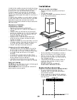
h
20”
30“
36“
17- 4/16”
28- 25/32”
30” Gas Cooktop (minimum)
24”-30“ Electric Cooktop (min)
h
Product Dimensions & Clearances


