background image

Page 5

On/Off Plug-In Switch Advanced User Manual

Specifications

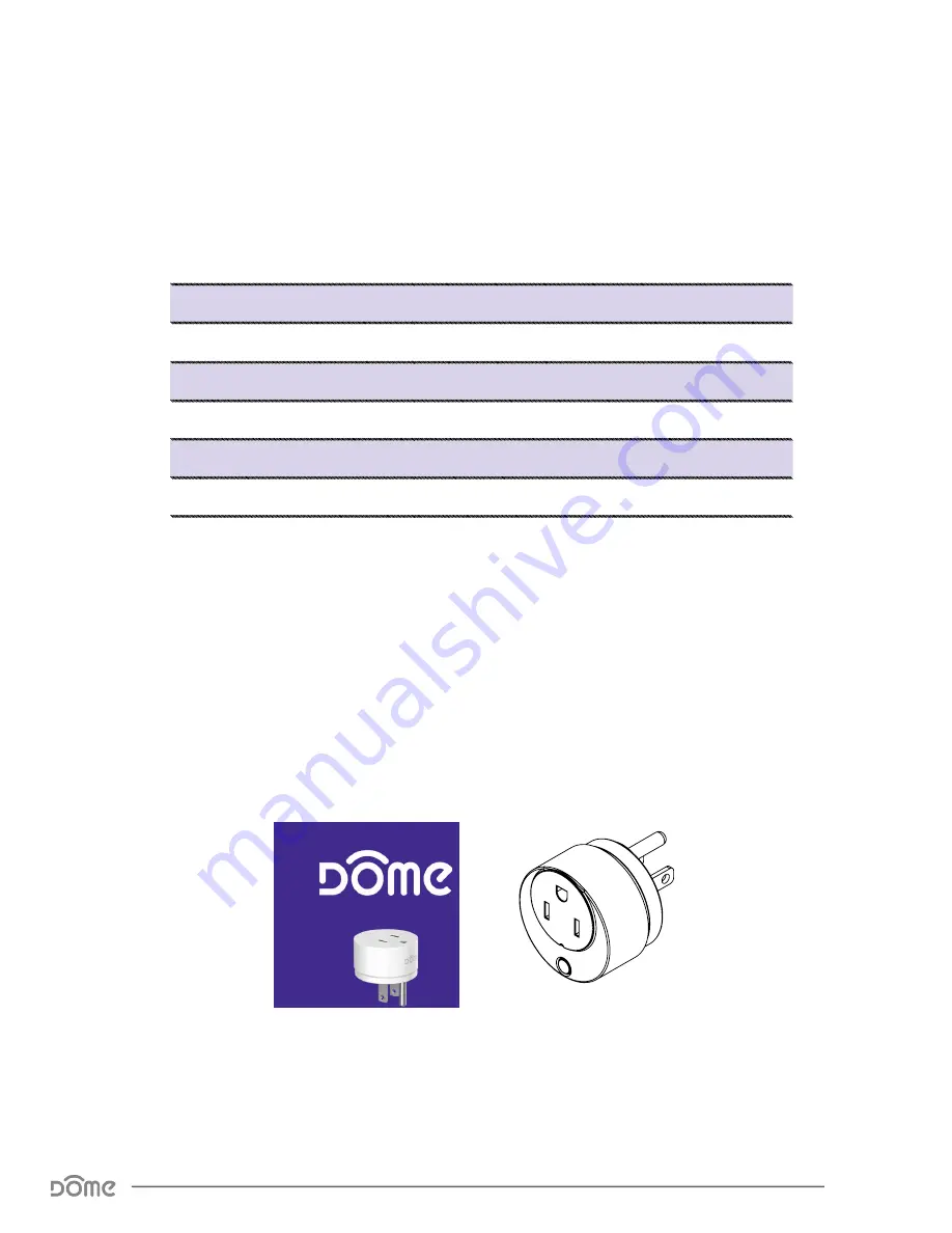
Package Contents:

Technical Specifications

Radio protocol

Z-Wave Plus (500 series)

Power supply

110-230V AC 50/60Hz

Max Current

13A

Power Consumption

0.13W

Radio frequency

908.4 MHz US

Z-Wave Range

Up to 150’ depending on environment

Dimensions (L x W x H)

1.8” x 1.8” x 1.8”

Table 1 - 

Technical Specifications

USER MANUAL

On/Off Plug-In Switch

Thank you for purchasing the DOME 

On/Off  Plug-In Switch, which works with your 

Z-Wave Certifi ed Controller to turn on and off  

any plugged in electronic device and monitor its 

power consumption.

SolidWorks Student Edition.

 For Academic Use Only.

Connect Button

DEVICE PORT

PLUG

Including/Connecting into the Z-Wave Network:

Follow the instructions for your Z-Wave certifi ed Controller 

to enter inclusion mode. 
When prompted by the Controller:
1.  For proper inclusion, bring the On/Off  Plug-In Switch 

to within 10 feet of your Controller and plug it in. After 

inclusion, the device can be moved to any desired 

location.

2.  Press the Connect Button quickly 3 times in a row.
The LED Indicator will fl ash fi ve times indicating inclusion.

Excluding/Disconnecting from the Z-Wave Network:

Follow the instructions for your Z-Wave certifi ed Controller to 

enter exclusion mode.When prompted by the Controller:

1.  Plug in the On/Off  Plug-In Switch within range of your 

Z-Wave Controller.

2.  Press the Connect Button quickly 3 times in a row.

The LED Indicator will fl ash fi ve times indicating exclusion/dis-

connection.

Resetting the On/Off  Plug-In Switch to Factory Default 

Settings:

To disconnect from the Z-Wave Network and restore factory default 

settings:

1.  Plug in the On/Off  Plug-In Switch.

2.  Hold the Connect Button for 10 seconds until the LED Indicator 

blinks once, then release the button.

Only do this if the controller is disconnected or otherwise unreach-

able!

Overload Protection:

The On/Off  Plug-In Switch shuts off  power and the LED Indicator 

will turn red when a current higher than 13 Amps passes through. 

To restore power after a current overload, power cycle the plug 

either by pressing the physical button or through your Z-Wave 

controller. You can also reboot the plug by unplugging it from the 

outlet.

On/Off  Plug-In Switch

SolidWorks Student Edition.

 For Academic Use Only.

Specifications

Summary of Contents for DOME DMOF1

Page 1: ...Always Connected Always Covered On Off Plug In Switch User Manual DMOF1 ...

Page 2: ...ic user please visit www domeha com for instructions This manual will provide in depth technical information about the On Off Plug In Switch especially in regards to its compli ance to the Z Wave standard such as compatible Command Classes Associa tion Group capabilities special features and other information that will help you maximize the utility of this product in your system Preface ...

Page 3: ...e 2 Description Features 4 Specifications 5 Physical Characteristics 6 Inclusion Exclusion 7 Factory Reset Misc Functions 8 Physical Installation 9 LED Behavior 10 Button Behavior 11 Compatible Command Classes 12 Configuration Command Class Parameters 16 Troubleshooting 19 Warranty Support 20 ...

Page 4: ...es and reports the data to your Z Wave Hub Key Features Z Wave Plus Certified Turns on or off any plugged in device Extends the range of your Z Wave system Up to 150 wireless range depending on environment Small size won t block the adjacent outlet Fits any standard 3 prong American power outlet Reports energy consumption data Overload protection Max current 13 A Event based response requires use ...

Page 5: ...nnecting into the Z Wave Network Follow the instructions for your Z Wave certified Controller to enter inclusion mode When prompted by the Controller 1 For proper inclusion bring the On Off Plug In Switch to within 10 feet of your Controller and plug it in After inclusion the device can be moved to any desired location 2 Press the Connect Button quickly 3 times in a row The LED Indicator will flash...

Page 6: ... Characteristics The names used in Figures 1 2 will be used throughout this manual Please refer to this page as needed Student Edition mic Use Only BUTTON DEVICE PORT PLUG Figure 1 On Off Plug In Switch Parts DMOF1 Figure 2 Bottom View Physical Characteristics ...

Page 7: ...red location after the inclusion process 2 When prompted by the controller quickly press the BUTTON 3 times 3 A yellow LED will flash five times indicating inclusion Exclusion Follow the instructions for your Z Wave Certified Conto enter exclusion mode When prompted by the controller 1 Plug the On Off Plug In Switch into an outlet 10 from your controller 2 Press the BUTTON quickly 3 times in a row...

Page 8: ...disconnected or otherwise unreachable Beware that resetting your device will disconnect it from the sys tem 1 Confirm that your On Off Plug In Switch is powered up 2 Press and hold the BUTTON for at least 10 seconds then release The LED will blink once in a red color followed by 5 times in a pink color indicating a successful factory reset 3 The On Off Plug In Switch s memory will be erased to fac...

Page 9: ...The On Off Plug In Switch can be installed in any standard 3 prong American power outlet To control or monitor an electronic device simply plug it into the DEVICE PORT Make sure there is sufficient Z Wave coverage in your desired installation location Physical Installation ...

Page 10: ...twork Yellow Blink 5 times in 500ms the BUTTON is pushed three times including the On Off Plug In Switch into a Z Wave network Always On the current is above the limit set in Param 4 12A by default Red Blink Once the BUTTON is pressed for an extended period of time resetting the On Off Plug In Switch to factory default settings Blink Once a Second the current is above the limit set in Param 3 13A ...

Page 11: ...n System Device sends node info to Group 1 On Off Plug In Switch Already Included in System and Controller is in Exclusion Mode Device is excluded from the z Wave Network On Off Plug Not Yet Included in System Device enters inclusion mode Press and Hold for 10 seconds All conditions Device will be reset to factory settings and a DEVICE_RESET_LOCALLY command will be sent to Node 1 Table 3 Button Be...

Page 12: ...on 01 Role Type 05 Slave Always On Node Type 00 Z Wave Plus Node Installer Icon Type 07 00 Generic Relay Device User Icon Type 07 00 Generic Relay Device Version V2 86 Returned Value 03 04 05 03 46 41 00 Z Wave Library Type 03 Enhanced Slave Protocol Version 04 05 Protocol Sub Version 03 46 Application Version 41 Application Sub Version 00 Manufacturer Specific V2 72 Returned Value 02 1F 03 01 03 ...

Page 13: ...l set in Parameter 3 When the current drops below the level again a BASIC_SET 00 command is sent to reset the device e g turn off the siren This Group can hold five devices Group 3 The On Off Plug In Switch sends Notification Reports to Group 3 and it can hold five devices Notification V4 71 The On Off Plug In Switch sends a NOTIFICATION_REPORT to Group 1 when the current load passes the level set...

Page 14: ...on 21 44 0010 0001 0100 0100 Scale 2 0 Rate Type 01 Import Consumed Meter Type 0 0001 Electric Meter Precision 010 2 decimal places Scale 1 0 0 0 Size 100 4 Bytes Scale Summed 0 0 0 Kilowatt Hours Meter Value 80 00 00 00 7F FF FF FF 2 147 483 648 2 147 483 647 in kWh Delta Time 00 00 FF FF 0 65 535 in seconds Previous Value 80 00 00 00 7F FF FF FF 2 147 483 648 2 147 483 647 in kWh Scale 2 00 Retu...

Page 15: ... Delta Time 00 00 FF FF 0 65 535 in seconds Previous Value 80 00 7F FF 32 768 32 767 in V Scale 2 00 Returned Value A1 4A XX XX YY YY ZZ ZZ 00 Scale Rate Type Meter Type Size Precision A1 4A 1010 0001 0100 1010 Scale 2 1 Rate Type 01 Import Consumed Meter Type 0 0001 Electric Meter Precision 010 2 decimal places Scale 1 0 0 1 Size 010 2 Bytes Scale Summed 1 0 1 Amperes Meter Value 80 00 7F FF 32 7...

Page 16: ..._ MANAGEMENT_OVER_LOAD_DETECTED signal to Group 1 and a BASIC_SET FF to Group 2 The LED will then blink red once per second until the current returns to normal To clear the NOTIFICATION and start monitoring again the BUTTON must be pushed once only after the current is back to normal NOTE this value must be higher than Param 4 01 Set Overload Current Level 01 10 1 16 in amps 0D 13 Amps Table 8 On ...

Page 17: ...This parameter sets this minimum current change amount in percent at which point the On Off Plug In Switch will send a METER_REPORT to Group 1 Also see Param 1 2 01 Current change METER_REPORT level 01 64 1 100 in change in amps 05 5 07 This parameter sets whether or not the On Off Plug In Switch will remember if it was turned on or off when it was last plugged in If enabled whenever the device is...

Page 18: ...efore the On Off Plug In Switch automatically shuts off See Param 8 02 Set Timer Time Interval 00 01 FF FF 1 65535 in Minutes 00 96 150 min 0A If this parameter is enabled the user can turn the device on or off using the BUTTON 01 Enable Disable BUTTON 00 Disable Button 01 Enable Button 01 Button Enabled Table 10 On Off Plug In Switch Configuration Parameters cont d ...

Page 19: ... Quick Start Guides have all you need to start using any device For more thorough information about Z Wave home automation visit www domeha com support Q Q I ve tried multiple times but I can t include the On Off Plug In Switch in my system A A Make sure your device is getting power Then follow the procedure to Factory Reset on Page 8 and try going through the inclusion process again If you are st...

Page 20: ...nly normal use in the United States or Canada To obtain warranty service during the Warranty Period call Dome Customer Service 1 855 249 1754 or email support domeHA com for instructions on sending damaged parts and documentation for a Return Material Authorization RMA Products returned to ECP for repair or replacement without au thorization will be returned at the sender s expense All warran ty c...

Reviews: