20
elements
enabling technologies for Life Science
SECTION 3 –
Software installation and description
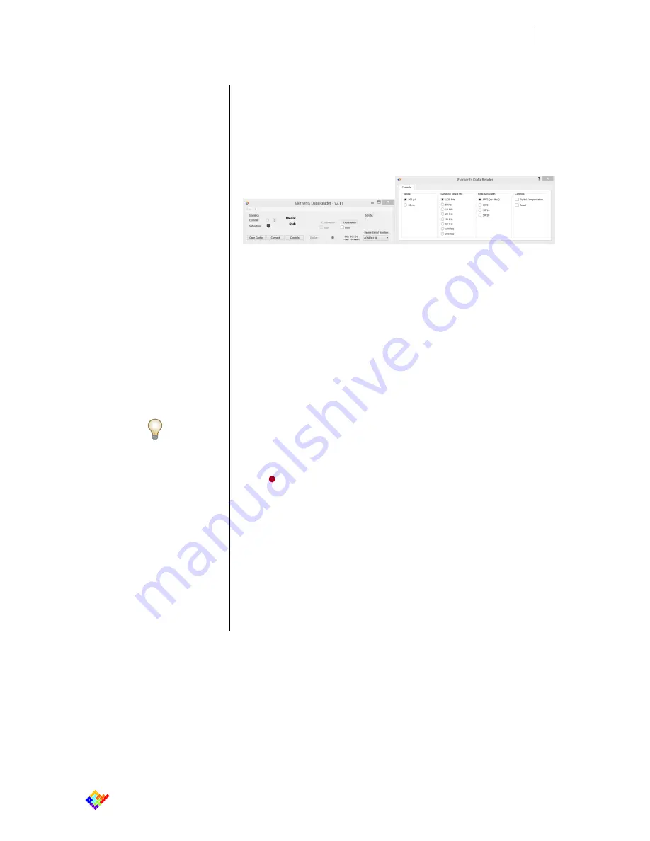
Figure 11
Elements Data Reader Complete GUI
Note:
Multiple instances of the software can run
on the same PC enabling to control several
eONE devices connected to the same PC. If
more than one eONE device are connected,
you must first choose the correct device Se-
rial Number to be controlled.
3.1.4
Graphical User Interface
After loading the config file, the GUI appears as follows:
In the main menu you can find some estimated statistic values on the input signal
(see the “Statistic Data” section for details) and, on the right there are the con-
trols to associate an oscilloscope-like trace (beam) with a specific input signal in
the Display window (in the case of eONE devices, there is only one input channel
available). See the “Trace Visualization” section for details.
On the right of the main menu there is also an estimation of the input bitrate.
In the bottom you can find, in addition to the “Open Config” button already de-
scribed in the previous section, the following buttons:
Connect
– Starts the communication with the eONE hardware.
Controls
– Opens the Controls window which presents the eONE device
specific commands (see the “eONE Controls” section for details).
Display
– Opens the Displays window in which data are visualized in real-
time.
Recording
– Saves data in the format and path selectable in the
“File
Preferences” menu.
In the bottom-right corner there is a drop-down list of the serial numbers of all
the recognized eONE devices connected to the PC.
To start acquiring data, click on the “
Connect
” button. Once connected, the
“Warning: voltage offset not compensated” message in the main menu starts
blinking to remember users to compensate the offset (see the “Digital Offset
Compensation” section for details)
Summary of Contents for eONE
Page 4: ......


