background image

15

EN

Operating and assembly instructions RDF

www.elektror.com

9016315 01.20/12

•  Other standards and regulations must be observed 

  depending on the application.
•  Blower feet and consoles must be designed only for the 

  respective blower’s own weight.
•  Cover the open air intake and discharge with protective 

  grilles according to DIN EN ISO 13857.
•  Ensure that the motor has adequate ventilation. 

  Permitted ambient temperatures with:

  Standard model with Elektror motor and a rated voltage of 

  50 Hz or 60 Hz:

  • Ambient temperature -20°C to +60°C

Note!

The rated e

  ciencies and the e

  ciency classes 

of the motors are given as per IEC 60034-2-1 for 

operation at an ambient temperature of 25°C.

As per IEC 60038 Elektror motors are generally 

designed for an extended voltage range of ±10%. 

However, the stated e

  ciency relates to the rated 

voltage, i.e., the extended tolerance is not taken 

into account.

Special voltages, multi-voltage motors, models suitable for 

frequency converters, FUK models, devices with UL ap-

proval, devices with Aircontrol and other motor makes:
  • Ambient temperature -20°C to +40°C
  • Voltage tolerance ±5% (For exceptions, see „4.2 Fre-
quency converter operation“)
•  The drive motor ventilation system must not be a

 ected 

  by the installation situation.

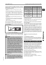
Minimum distance to the blower cover (for the intake of 

cooling air)

Drive power

Minimum distance 

to the blower cover 

[mm]   

[inches]

 1.5 kW

34

1.34

> 1.5 kW

53

2.09

3.3 Electrical connection

Note!

The work described in this section may only be 

performed by a quali

fi

 ed electrician. Connect ac-

cording to the wiring diagram placed in the termi-

nal box complying with relevant local regulations.

Three-phase or a.c. motors can be used as drive motors. 

In the appliance designation, the letter D stands for three-

phase a.c. and the letter E for single-phase a.c.
•  The drive motor must be protected using a motor overload 

  switch (this does not apply to frequency converter oper-

 ated appliances). Where appliances are frequency-

  converter-operated, the existing temperature sensor (PTC 

  resistor sensor) or temperature switch (normally closed 

  contact) must be connected to the converter and evalu-

 ated.
•  The safety earth terminal can be found in the terminal box.
•  Install Electrical ON/OFF switches that can be locked as 

  maintenance / repair switches.
•  Suitable electrical controlling must ensure the blower runs 

  long enough to clear the line system of any residual media 

  and avoid its blockage.
•  Check that the mains voltage corresponds to the voltage

 speci

fi

 ed on the nameplate.

Note!

The following information should also be ob-

served when operating the drive motor with a 

frequency converter:
• Only motors must be used on the frequency 

converter that are marked on the rating plate with 

the option “/FU”, “suitable for use with a frequen-

cy converter” or that were ordered and con

fi

 rmed 

as “suitable for use with a frequency converter”.
• The frequency converter supply voltage must 

only be a maximum of 400 V without the motor 

fi

 l-

ter. Appropriate measures such as a motor 

fi

 lter to 

protect the motor must be installed on the motor 

terminals with higher frequency converter supply 

voltages, longer lines and/or if the pulse voltages 

are exceeded (max. 1000 Vpk for drive motors up 

to 0.75 kW, maximum 1300 Vpk for drive motors 

larger than 0.75 kW)  Please contact the converter 

supplier in this case. If a motor 

fi

 lter is included 

in the delivery, this must be installed between 

the converter and the motor. Please ensure that 

there is su

  cient space in the switch cabinet and 

take into account the installation and assembly 

requirements in the operating instructions of the 

frequency converter/motor 

fi

 lter manufacturer.

• The maximum cable length between the mo-

tor and switch cabinet frequency converter (e.g. 

Lenze Vector, Omron MX2 and Omron RX) must 

not exceed 20 m. Maximum cable lengths of up to 

3 m are permitted with Kostal INVEOR frequency 

converters installed close to the motor and up to 

10 m with Lenze MOTEC frequency converters. 

Further information on wall mounting close to the 

motor can be found in the original operating and 

assembly instructions of the respective frequen-

cy converter manufacturer. The electrical con-

necting cables between the motor and frequency 

converter in the above cases must be suitable 

shielded cables, laid using the shortest route and 

without clamping and plug-in connections and 

connected correctly at both sides. 
• The shielding braid in the connecting cables 

must be connected fully, continuously and on 

both sides, i.e. to the frequency converter and 

motor, and at low resistance and permanently to 

protective earthing systems or the main earthing 

bus bar. Suitable EMC cable glands must be used 

for this on the motor side and also on the INVEOR 

wall mounting plate, if necessary. 
• It is important to ensure that the solid con-

nection of the device to the protective earthing 

system or several suitable earthing lines is at low 

resistance and permanent for blowers installed 

with electrical insulation (e.g. through vibration 

dampers, compensators, insulated pipes, etc.) for 

frequency converter operation.

For further information about EMV compliant installation refer 

to the operating and assembly instructions of the frequency 

converter’s manufacturer.

3.3.1 Con

fi

 guration for three-phase current blowers

Warning!
Danger due to loose or improperly tightened con-

nections!
Improperly tightened and loose connections 

cause electric shocks, 

fi

 res, property damage and 

personal injuries!
Check for loose connections and tighten in 

accordance with the tightening torques in the fol-

lowing table.

Summary of Contents for RD 14 F

Page 1: ...48 Ostfildern Telefon 49 711 31973 0 Telefax 49 711 31973 5000 info elektror de www elektror de RD F RD 14 F RD 4 F RD 5 F RD 6 F RD 62 F RD 64 F RD 74 F RD 82 F Elektror Förder ventilatoren Betriebs und Montageanleitung DE Elektror Convey ing Blowers Operating and assembly instructions EN ...

Page 2: ...t stoffgranulat Kunststoffabfällen sowie leichten Schüttgütern aller Art Stoffe oder Stoffgemische von denen beim Betrieb besondere Gefahren ausgehen können dürfen nicht geför dert werden z B brennbare Stäube explosible Stoffe che misch instabile Stoffe oder Stoffgemische die miteinander reagieren können Die Förderventilatoren eignen sich nicht zur Aufstellung in oder Förderung von explosionsfähiger At m...

Page 3: ...st dieser entsprechend DIN EN ISO 13857 mit einem Berührungsschutz zu versehen Dieser Berührungsschutz muss als zusätzliches Ausrüstungsteil gesondert bestellt werden 1 8 Sicherheitshinweise zur Reinigung und Wartung Warnung Reinigungs und Wartungs Reparaturarbeiten dürfen erst nach Stillstand des Laufrades vorge nommen werden Elektrische Ein Ausschalter als Wartungs Reparaturschalter müssen ab sc...

Page 4: ...n Ventilator nicht ungeschützt im Freien lagern vor Feuchtigkeit schützen Hebezeug sicher anschlagen Nur Hebezeuge und Lastaufnahmeeinrichtungen mit ausreichender Tragfähig keit verwenden Transportwege sichern Hinweis Die Ringschraube am Motor darf nicht zum Anheben des Gesamtventilators verwendet werden Diese wird für eine evtl Motor de montage verwendet Hinweis Bei Geräten mit aufgebauten Freque...

Page 5: ...er Elektrofachkraft ausge führt werden Anschluss nach dem Schaltbild im Klemmenkasten und den einschlägigen örtlichen Bestimmungen vornehmen Als Antriebsmotoren kommen Dreh oder Wechselstrom motoren zum Einsatz In der Gerätekennzeichnung ent sprechen die Buchstaben D Drehstrom 3 und E Einpha sen Wechselstrom 1 Der Antriebsmotor ist mit einem Motorschutzschalter abzusichern gilt nicht für Frequenzu...

Page 6: ...k Anlauf am Ver sorgungsnetz vorgesehen Für direktes Einschalten hoher Kurzschlussstrom im Einschaltaugenblick bitte die Bedin gungen mit Ihrem Energieversorgungsunternehmen klären 3 3 2 Schaltung für Einphasen Wechselstrom Ventilatoren Rechtslauf Linkslauf 3 4 Sonderverschaltungen und Zusatzklemmen Für Spannungsumschaltbare Motore Polumschaltbare Mo toren FU FUK Motoren und sonstige Sonderverscha...

Page 7: ... kHz betragen da eine geringere Pulsfrequenz starke Motorgeräusche erzeugt Die Werte zu den Maximal Mindestfrequenzen stehen unter 1 13 Der Umrichter muss einen Anschluss für Temperatur fühler PTC Kaltleiterfühler oder einen Temperatur wächter Öffnerkontakt haben Werte siehe Leistungsschild Der Motor kann in Dreieck oder Sternschaltung je nach Eingangsspannung des Umrichters betrieben werden Unbedi...

Page 8: ...frad sind rechtzeitig auszutauschen da durch ungleiche Abnützung eine erhebliche Unwucht entste hen kann welche zum Ausfall der Lager führt 5 2 Laufradwechsel und Reinigungsarbeiten erfolgen durch Abschrauben des Gehäusedeckels Bei diesen Arbeiten ist die elektr Stromzuführung zu unterbrechen Das Laufrad muss sich dazu im Stillstand befinden und gegen Wiederan lauf gesichert sein 5 3 Wartungsarbei...

Page 9: ...m Edel Stahl Kupfer und Kunststoff Es gibt je doch auch Bauteile die eine besondere Behandlung bedür fen z B Frequenzumrichter Gesetzliche nationale und örtliche Entsorgungs und Recyc lingvorschriften müssen eingehalten werden 7 HAFTUNG UND HAFTUNGSAUS SCHLUSS Die Verantwortung für die bestimmungsgemäße Verwen dung des Gerätes trägt der Betreiber Die Fa Elektror lehnt jede Haftung für nicht bestimm...

Page 10: ... bis festgestellt wurde dass die Maschine in die die unvoll ständige Maschine eingebaut werden soll den Bestimmungen der Maschinenrichtlinie 2006 42 EG entspricht Die folgenden harmonisierten Normen wurden angewandt DIN EN ISO 12100 2011 Sicherheit von Maschinen allgemeine Gestaltungsleitsätze Risikobeurteilung und Risikominimierung DIN EN 60034 1 2011 Drehende elektrische Maschinen Teil 1 Bemessu...

Page 11: ...11 www elektror de Betriebs und Montageanleitung RD F 9016315 01 20 12 DE ...

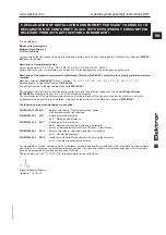
Page 12: ...ically unstable or substances that may react with each other The blowers are not suitable to convey or to be used in a potentially explosive atmosphere Use of the blowers for aggressive abrasive sticky toxic potentially explosive or very moist media is not permissible For the standard version the temperature of the conveyed media must not be below 20 C and not exceed 80 C The blower is not suitabl...

Page 13: ... touching danger of burns In the case of high power models in particular the tempera ture of the conveyed medium can increase as it flows from the intake side to the exhaust side The temperature differ ence can be in the region of up to 20 C depending on the operating conditions This varies from one model to another 1 10 Motor circuit breaker Before commissioning the blower a motor overload switch ...

Page 14: ...ther start up the proper operating status of the unit must be inspected Units that for example are found to be defective upon delivery or during installation must be examined by qualified techni cians Installation assembly and operation must only be performed by properly trained and qualified specialists Operation fol lowing incorrect installation maintenance or unapproved replacement of component...

Page 15: ... are marked on the rating plate with the option FU suitable for use with a frequen cy converter or that were ordered and confirmed as suitable for use with a frequency converter The frequency converter supply voltage must only be a maximum of 400 V without the motor fil ter Appropriate measures such as a motor filter to protect the motor must be installed on the motor terminals with higher frequen...

Page 16: ... are observed in order to meet the requirements of the EC Electromagnetic Compatibility Di rective 2014 30 EU If the device is delivered together with a frequency converter package for switch cabinet or wall mounting closer to the mo tor it is possible to comply with EN 61800 3 category C2 In dustrial environments taking into consideration the above mentioned EMC instructions Warning This product ...

Page 17: ...output class see rating plate with run up expiry as well as speed changes in order to to avoid high component loads and faults in the converter operation Device motor output Run up time s Expiry time s Motor output 0 25 kW 5 10 0 25 kW Motor output 3 0 kW 10 20 3 1 kW Motor output 7 5 kW 20 40 7 6 kW Motor output 11 0 kW 30 60 11 1 kW Motor output 30 0 kW 30 100 A uniform run up and expiry must be...

Page 18: ...ll cases and wait until all moving parts have stopped before opening reaching in or inserting tools into the device Secure the device reliably against it being accidentally restarted dur ing the entire period Also make sure that no other dangerous situation can arise when restarting after a standstill e g as a result of a power failure or blockages Cleaning or maintenance must not lead to damage o...

Page 19: ...fied that the machine in which the partially completed machine is to be installed complies with the provisions of the Machinery Directive 2006 42 EC The following harmonised standards were applied DIN EN ISO 12100 2011 Safety of machinery General principles of design Risk assessment and risk reduction DIN EN 60034 1 2011 Rotating electrical machines Part 1 Rating and performance DIN EN 60034 5 200...

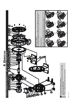
Page 20: ...tungsschild When ordering please state Serial no rating plate and blower type rating plate Gehäusestellungen Die Gehäusestellung des Ventilators ist für die Bestellung einiger Ersatztei le entscheidend Bestellen Sie Ersatzteile zur Drehrichtung passend Housing positions The position of the blower housing is important for ordering several spare parts Order spare parts which match the direction of r...

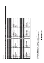
Page 21: ...acitor DE EN Pos Benennung Name 1 Schraube Screw 2 Gehäusedeckel Housing cover 3 Schraube Screw 4 Scheibe Disc 5 Laufrad Impeller 6 Ventilatorgehäuse Blower housing 7 Schraube Screw 8 Ventilatorfl ansch Blower fl ange 9 Radialwellendichtung Radial shaft seal 10 Distanzstück Spacer 11 Ventilationsfl ügel Blower blade 12 Gewindestift Grub screw 13 Schraube Screw 14 Flanschlagerschild Flange endshiel...

Page 22: ...100 3430 230 400 60 3 55 2 05 0 90 23 72 84 NEMA Premium 16 0 2100 3430 277 480 60 2 95 1 71 0 90 23 72 84 RD 5 F IE3 19 5 2200 2905 230 400 50 4 00 2 30 1 10 28 5 72 84 6204 6204 IE3 20 5 2400 3490 230 400 60 4 55 2 65 1 32 28 5 74 88 NEMA Premium 20 5 2400 3490 277 480 60 3 80 2 20 1 32 28 5 74 88 RD 6 F IE3 24 0 2500 2905 230 400 50 5 40 3 10 1 50 32 5 76 88 6205 6205 IE3 23 0 2500 3505 230 400...

Page 23: ...9 NEMA Premium 62 0 6800 3525 480 60 19 5 13 2 136 94 99 The values in the table apply only for motors of Elektror other brands may vary 1 min value max value of characteristic curve 2 A side B side standard designation Limiting deviation according to DIN 24166 accuracy class 3 Die Werte in der Tabelle gelten nur für Motoren von Elektror andere Marken können variieren 1 min Wert max Wert der Kennl...

Page 24: ... optimal energy effi ciency kW Volumetric fl ow rate at optimal energy effi ciency m3 min Total pressure diff erence at optimal energy effi ciency Pa Revolutions per minute at optimal energy effi ciency Specifi c relationship Information to simplify disassembly recycling or disposal after fi nal decommissioning Information on installation operation and maintenance of the ventilator to minimise its environm...

Page 25: ...ennz Beschreibung FU Mit diesem Ventilator muss eine Drehzahlregelung installiert werden FUK In diesem Ventilator ist eine Drehzahlregelung integriert 1 total effi ciency 2 3 refer to rating plate 4 Elektror airsystems gmbh Hellmuth Hirth Str 2 73760 Ostfi ldern Germany Tax number 5933041962 VAT ID No DE 250175973 District Court Stuttgart HRB 210469 5 refer to operating instruction 6 none Product la...

Page 26: ...26 9016315 01 20 12 ...

Page 27: ...27 9016315 01 20 12 ...

Page 28: ... Internet unter www elektror de Gerne steht Ihnen auch unser Produktmanagement unter der Rufnummer 49 711 31973 1111 zur Verfügung You will find further information about our products on the internet at www elektror com Our Product management staff will be pleased to answer your queries at 49 711 31973 1111 Hellmuth Hirth Strasse 2 D 73760 Ostfildern Postfach 12 52 D 73748 Ostfildern 49 711 31973 0...

Reviews: