Page 36
EA Elektro-Automatik GmbH
Helmholtzstr. 31-37 • 41747 Viersen
Germany
Fon: +49 2162 / 3785-0
Fax: +49 2162 / 16230
www.elektroautomatik.de
EL 9000 B 15U/24U Series
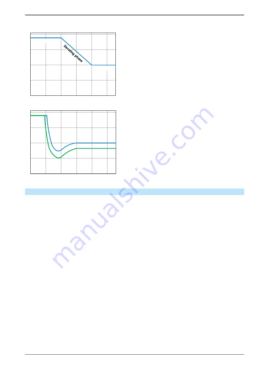
See the diagrams below for clarification.
0s
40s
80s
...
210s
Peak power
Steady power
Principle derating progression, depicted on the example of
one load unit. All models of this series have multiple load units
equipped which not necessarily start derating at the same time.
The peak power is absorbed by the load device for a time x,
until derating starts. After the start of derating, the max. power
of the load will settle around the point of steady power. The
momentary true value of steady power can only be read from
the device’s actual power value (display or via interface). In
case the ambient temperature rises, the derating will continue.
0s
80s
...
210s
Derating @ 25°C
Derating @ 40°C
Derating progression after a cold start of the device at 25°C
(blue) and 40°C (green) ambient temperature.
The temporal progression shows that the peak power at 40°C
is only available for a short time before derating starts. At this
ambient temperature, the steady power will settle at a lower
value than with 25°C.
3.2.5
Dynamic characteristics and stability criteria
The electronic load is characterized by short rise and fall times of the current, which are achieved by a high band-
width of the internal regulation circuit.
In case of testing sources with own regulation circuits at the load, like for example power supplies, a regulation
instability may occur. This instability is caused if the complete system (feeding source and electronic load) has too
little phase and gain margin at certain frequencies. 180 ° phase shift at > 0dB amplification fulfills the condition for
an oscillation and results in instability. The same can occur when using sources without own regulation circuit (eg.
batteries), if the connection cables are highly inductive or inductive-capacitive.
The instability isn’t caused by a malfunction of the load, but by the behavior of the complete system. An improve-
ment of the phase and gain margin can solve this. In practice, a capacity is directly connected to the DC input of
the load. The value to achieve the expected result isn’t defined and has to be found out. We recommend:
80 V models: 1000 μF....4700 μF
200 V models: 100 μF...470 μF
360 V models: 68 μF...220 μF
500 V models: 47 μF...150 μF
750 V models: 22 μF...100 μF


