

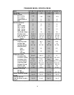


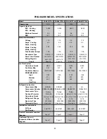
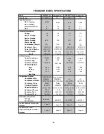
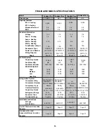


FRIGIDAIRE MODEL SPECIFICATIONS
6
Power Cord Number
Page #
High
Medium
Low
Heat Only
Model
Chassis type
Capacity features
BTU - Cooling
BTU - Heating
Moisture Removal
EER
Electrical Information
Voltage
Amps - Cooling
Amps - Heating
Watts - Cooling
Watts - Heating
Fuse/Breaker (Amps)
Receptacle Type
Wiring Diagram
Fan Motor Number
RPM/CMP (EVAP)
Air Flow System
Capacitor-µ farads
Fan Motor Mfg.
Refrigeration System
Compressor Mfg.
Compressor Number
Compressor Type
Part Number
Overload Protector
Capacitor-µ farads
Refrigerant Charge
Restrictor Tube
Thermostat Type
Installation Instructions
Kit Type
Diagram
Control Thermostat Location
Diagram
Condenser Fan and
Evaporator Blower Location
03001280
9.87
Electronic
64611008
KB
NF
KB
NF
FAX054P7A-1
40020558
0.4
9.7
5.2
515
1370
1270
1150
SENLIN
BF900-KB
63611326
35/8uF 370V
15011035
8/250
5,000
-
115
-
-
15A
Page
32
-
Rotary
NEM
A
5-15
-
OPP5
SD074SW-H3BD
03001280
9.87
03001274
9.87
03001274
9.87
Electronic
64611008
64611008
64611008
FAX054P7A-2
40020558
0.4
9.7
5.2
515
1370
1270
1150
SENLIN
BF900-KB
63611326
35/8uF 370V
15011035
8/250
5,000
-
115
-
-
15A
Page
32
-
Rotary
NEM
A
5-15
-
OPP5
SD074SW-H3BD
FAX054P7A-4
40020558
0.4
9.7
5.2
515
1370
1270
1150
LG
63611326
35/8uF 370V
15011035
8/250
Electronic
Electronic
5,000
-
115
-
-
15A
Page
32
-
Rotary
NEM
A
5-15
-
MRA12112-12026
OPP5
QA075CDE
FAX054P7A-5
40020558
0.4
9.7
5.2
515
1370
1270
1150
LG
63611326
35/8uF 370V
15011035
8/250
5,000
-
115
-
-
15A
Page
32
-
Rotary
NEM
A
5-15
-
MRA12112-12026
OPP5
QA075CDE
P
age 46
P
age 56
P
age 46
P
age 56
P
age 46
P
age 56
P
age 46
P
age 56
Summary of Contents for FAA055P7A-1
Page 32: ...32 63611621 63611326 ...
Page 33: ...33 63611618 63611620 ...
Page 34: ...34 63611619 M1 M2 63611613 ...
Page 35: ...35 63611329 63611614 ...
Page 36: ...36 633611615 63611622 ...
Page 37: ...37 63611616 63611091 ...
Page 38: ...38 63611642 ...
Page 39: ...39 63611328 ...
Page 40: ...40 63611094 63611629 ...
Page 41: ...Control Thermostat Location diagram for Heavy Duty 41 ...
Page 42: ...Control Thermostat Location diagram for Median 42 ...
Page 43: ...Control Thermostat Location diagram for Slider Casement 43 ...
Page 44: ...Control Thermostat Location diagram for TTW 44 ...
Page 45: ...The 5th pipe The 4th pipe 160cm Control Thermostat Location diagram for COM2 45 ...
Page 46: ...The 5th pipe The 4th pipe 130cm Control Thermostat Location diagram for OPP5 46 ...
Page 47: ...The 5th pipe The 4th pipe 160cm Control Thermostat Location diagram for MS2 47 ...
Page 48: ...Condenser Fan and Evaporator Blower Location Diagram for TTW 1 48 ...
Page 49: ...Condenser Fan and Evaporator Blower Location Diagram for Slider Casement 1 49 ...
Page 50: ...Condenser Fan and Evaporator Blower Location Diagram for Heavy Duty 1 50 ...
Page 51: ...Condenser Fan and Evaporator Blower Location Diagram for Median 1 51 ...
Page 52: ...Condenser Fan and Evaporator Blower Location Diagram for TTW 2 52 ...
Page 53: ...Condenser Fan and Evaporator Blower Location Diagram for Slider Casement 2 53 ...
Page 54: ...Condenser Fan and Evaporator Blower Location Diagram for Median 2 54 ...
Page 55: ...Condenser Fan and Evaporator Blower Location Diagram for Heavy Duty 2 55 ...
Page 56: ...Condenser Fan and Evaporator Blower Location Diagram for OPP5 56 ...
Page 57: ...Condenser Fan and Evaporator Blower Location Diagram for MS2 57 ...
Page 58: ...Condenser Fan and Evaporator Blower Location Diagram for COM2 58 6cm 8cm ...


