


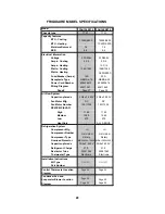

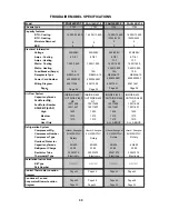


FAH126R2T-1 FAH12ER2T-1
TTW
TTW
12,000/11,500 12,000/11,500
- 10
,6
00/8,600
1.6
1.6
9
9
230V/208V 230V/208V
6.7/6 6.7/6
- 16/14.5
1,335/1,275 1,335/1,275
- 3,450/2,850
15A 20A
NEM
A
6-15A NEM
A
6-20A
Power Cord Number
63611091
63611642
400205613 400205614
Page #
Page 3
7
Page 3
8
30/6uF 450V 30/6uF 450V
DY DY
150110392
150110392
High
1330 1330
Medium
1200 1200
Low
1080 1080
Heat Only
- ALL ABOVE
LG
LG
QK164KBD
QK164KBD
Rotary
Rotary
MRA12124-12026
30/6uF 450V 30/6uF 450V
30.7 30.7
03001060
03001060
29
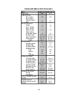
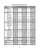
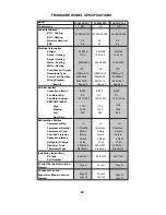
Condenser Fan and
Evaporator Blower Location
Diagram
Kit Type
Part Number
Control Thermostat Location
Diagram
Refrigerant Charge
Restrictor Tube
Thermostat Type
Installation Instructions
Compressor Number
Compressor Type
Overload Protector
Capacitor-µ farads
Fan Motor Number
RPM/CMP (EVAP)
Refrigeration System
Compressor Mfg.
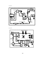
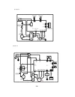
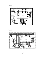
Wiring Diagram
Air Flow System
Capacitor-µ farads
Fan Motor Mfg.
Watts - Cooling
Watts - Heating
Fuse/Breaker (Amps)
Receptacle Type
Electrical Information
Voltage
Amps - Cooling
Amps - Heating
BTU - Cooling
BTU - Heating
Moisture Removal
EER
FRIGIDAIRE MODEL SPECIFICATIONS
Model
Chassis type
Capacity features
MRA12124-12026
Electronic
Electronic
51061057
51061057
P
age 44
P
age 48
P
age 44
P
age 48
P
age 52
P
age 52
Summary of Contents for FAA055P7A-1
Page 32: ...32 63611621 63611326 ...
Page 33: ...33 63611618 63611620 ...
Page 34: ...34 63611619 M1 M2 63611613 ...
Page 35: ...35 63611329 63611614 ...
Page 36: ...36 633611615 63611622 ...
Page 37: ...37 63611616 63611091 ...
Page 38: ...38 63611642 ...
Page 39: ...39 63611328 ...
Page 40: ...40 63611094 63611629 ...
Page 41: ...Control Thermostat Location diagram for Heavy Duty 41 ...
Page 42: ...Control Thermostat Location diagram for Median 42 ...
Page 43: ...Control Thermostat Location diagram for Slider Casement 43 ...
Page 44: ...Control Thermostat Location diagram for TTW 44 ...
Page 45: ...The 5th pipe The 4th pipe 160cm Control Thermostat Location diagram for COM2 45 ...
Page 46: ...The 5th pipe The 4th pipe 130cm Control Thermostat Location diagram for OPP5 46 ...
Page 47: ...The 5th pipe The 4th pipe 160cm Control Thermostat Location diagram for MS2 47 ...
Page 48: ...Condenser Fan and Evaporator Blower Location Diagram for TTW 1 48 ...
Page 49: ...Condenser Fan and Evaporator Blower Location Diagram for Slider Casement 1 49 ...
Page 50: ...Condenser Fan and Evaporator Blower Location Diagram for Heavy Duty 1 50 ...
Page 51: ...Condenser Fan and Evaporator Blower Location Diagram for Median 1 51 ...
Page 52: ...Condenser Fan and Evaporator Blower Location Diagram for TTW 2 52 ...
Page 53: ...Condenser Fan and Evaporator Blower Location Diagram for Slider Casement 2 53 ...
Page 54: ...Condenser Fan and Evaporator Blower Location Diagram for Median 2 54 ...
Page 55: ...Condenser Fan and Evaporator Blower Location Diagram for Heavy Duty 2 55 ...
Page 56: ...Condenser Fan and Evaporator Blower Location Diagram for OPP5 56 ...
Page 57: ...Condenser Fan and Evaporator Blower Location Diagram for MS2 57 ...
Page 58: ...Condenser Fan and Evaporator Blower Location Diagram for COM2 58 6cm 8cm ...


