
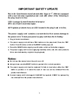


IMPORTANT SAFETY UPDATE
Room Air Conditioners manufactured after August 1
st
, 2004 are equipped
with a new industry regulated power cord with either of the following in
the plug-head or in line:
LCDI: Leakage Current Detection Interrupter
AFCI: Arc-Fault Circuit Interrupter.
All Frigidaire products have an LCDI located in the plug head or in-line.
The power supply cord contains a current device that senses damage to
the power cord. To test your power supply cord does the following:
1. Plug in the Air Conditioner.
2. The power supply cord will have TWO buttons on the plug head. Press the TEST
button. You will notice a click as the RESET button pops out.
3. Press the RESET button. Again you will notice a click as the button engages.
4. The power supply cord is now supplying electricity to the unit. (On some products
this is also indicated by a light on the plug head).
Notes:
●
Do not use this device to turn the unit on or off.
●
Always make sure the RESET button is pushed in for correct operation.
●
The power supply cord must be replaced if it fails to reset when either the TEST
button is pushed, or it cannot be reset. A new one can be obtained from the
product manufacturer.
●
If power supply cord is damaged, it CANNOT be repaired, it MUST be replaced by
one obtained from the product manufacturer.
3
Summary of Contents for FAA055P7A-1
Page 32: ...32 63611621 63611326 ...
Page 33: ...33 63611618 63611620 ...
Page 34: ...34 63611619 M1 M2 63611613 ...
Page 35: ...35 63611329 63611614 ...
Page 36: ...36 633611615 63611622 ...
Page 37: ...37 63611616 63611091 ...
Page 38: ...38 63611642 ...
Page 39: ...39 63611328 ...
Page 40: ...40 63611094 63611629 ...
Page 41: ...Control Thermostat Location diagram for Heavy Duty 41 ...
Page 42: ...Control Thermostat Location diagram for Median 42 ...
Page 43: ...Control Thermostat Location diagram for Slider Casement 43 ...
Page 44: ...Control Thermostat Location diagram for TTW 44 ...
Page 45: ...The 5th pipe The 4th pipe 160cm Control Thermostat Location diagram for COM2 45 ...
Page 46: ...The 5th pipe The 4th pipe 130cm Control Thermostat Location diagram for OPP5 46 ...
Page 47: ...The 5th pipe The 4th pipe 160cm Control Thermostat Location diagram for MS2 47 ...
Page 48: ...Condenser Fan and Evaporator Blower Location Diagram for TTW 1 48 ...
Page 49: ...Condenser Fan and Evaporator Blower Location Diagram for Slider Casement 1 49 ...
Page 50: ...Condenser Fan and Evaporator Blower Location Diagram for Heavy Duty 1 50 ...
Page 51: ...Condenser Fan and Evaporator Blower Location Diagram for Median 1 51 ...
Page 52: ...Condenser Fan and Evaporator Blower Location Diagram for TTW 2 52 ...
Page 53: ...Condenser Fan and Evaporator Blower Location Diagram for Slider Casement 2 53 ...
Page 54: ...Condenser Fan and Evaporator Blower Location Diagram for Median 2 54 ...
Page 55: ...Condenser Fan and Evaporator Blower Location Diagram for Heavy Duty 2 55 ...
Page 56: ...Condenser Fan and Evaporator Blower Location Diagram for OPP5 56 ...
Page 57: ...Condenser Fan and Evaporator Blower Location Diagram for MS2 57 ...
Page 58: ...Condenser Fan and Evaporator Blower Location Diagram for COM2 58 6cm 8cm ...


