background image

- 3 -

TSE-N 12.99 A. B.

599 50  72 16

EN

Attention

m

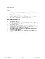
Please observe the applicable safety requirements according to DIN/VDE 0701
(concerning repairs) and VDE 0700/ICE 355 respectively VDE 0860/IEC 65 (concerning
type of product)!

m

Components to IEC or VDE guidelines! Only use components with the same
specification for replacement!

m

Controls with MOS components use only components with the same specification.

m

Observe MOS components handling instructions when servicing!

Recommendation for service repairs

m

Use only original spare parts.

With components or assemblies accompanied with the Safety Symbol  

 only origi-

nal-spare parts are strictly to be used.

m

Use only original fuse value.

m

Pay attention to ratings and power data of components and protective devices.

m

Safety compliance, parts of the product must not be visually damaged or unsuitable.
This is valid especially for insulators and insulating parts.

m

Mains leads and connecting leads should be checked for external damage before
connection. Check the insulation!

m

The functional safety of the tension relief and bending protection bushes are to be
checked.

m

Thermally loaded solder pads are to be suck off and re-soldered.

m

Ensure that the ventilation slots are not obstructed.

Safety instructions

Summary of Contents for EURO OVEN

Page 1: ...Edition SERVICE MANUAL AEG Hausgeräte GmbH Muggenhofer Straße 135 D 90429 Nürnberg Germany Fax 49 0 911 323 1420 TSE N Publ Nr 599 50 72 16 685 12 99 EURO OVEN EN WOEC Test program ...

Page 2: ...energy regulator 1 5 Circuit diagram of energy regulator 2 5 1 3 Oven control 5 Circuit diagram of oven thermostat 5 Thermotronic electronic oven control WOEC 5 1 4 WOEC test programmes and their application 6 Descriptions of programme 1 6 7 11 Fault finding 12 2 Service instructions 13 Dismantling front glass oven door and door handle 13 Rubber gasket between air duct and switch panel 14 ...

Page 3: ... parts With components or assemblies accompanied with the Safety Symbol only origi nal spare parts are strictly to be used m Use only original fuse value m Pay attention to ratings and power data of components and protective devices m Safety compliance parts of the product must not be visually damaged or unsuitable This is valid especially for insulators and insulating parts m Mains leads and conn...

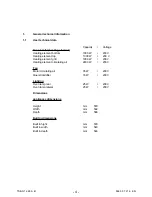
Page 4: ...nt top 1000 W 230 V Heating element grill 1900 W 230 V Heating element circulating air 2400 W 230 V Fan Motor circulating air 35 W 230 V Querstromlüfter 16 W 230 V Lighting Oven lamp rear 25 W 230 V Oven lamp lateral 25 W 230 V Dimensions appliances dimensions Height mm 579 Width mm 592 Depth mm 566 Built in dimensions Built in hight mm 579 Built in width mm 540 Built in depth mm 546 ...

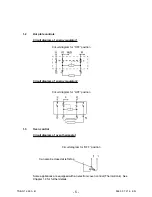
Page 5: ... Circuit diagram of oven thermostat Some appliances are equipped with an electronic oven control Thermotronic See Chapter 1 4 for further details Circuit diagram of energy regulator 2 Circuit diagram for OFF position Circuit diagram for OFF position Circuit diagram for OFF position Can also be closed at left stop ...

Page 6: ...tor for correct operation of the appliance If any deviation from the specified parameters is detected during this test the service symbol and a 3 digit service code are shown in the display In addition the appliance is switched on via safety relay K60 and the cooling fan via K61 The cooling fan cannot be switched off on the appliance as long as the above mentioned self test detects the fault The o...

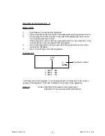
Page 7: ... no entry made for 5 s the control switches to the preselected test programme 4 Once a test programme has been executed this programme can be quit by pressing the Off button 5 See 1 for switching on the test programme Programme 1 in red 048 Programme number 1 Block 048 2 Block 900 3 Block 210 1 white The 9 digit code which appears in 3 successive blocks of 3 digits each is the version number of th...

Page 8: ...g on the assignment Attention If the load is switched on the switch on time should be kept short as neither the cooling fan nor the hot air ventilator are running and excessively long switch on times can cause damage Programme number 2 white 1 in red Relay number 1 Cooling fan K 61 16 W 0 07 A 2 Ring heater element K 62 2400 W 10 43 A 3 Not equipped 4 Grill K 64 1900 W 8 26 A 5 Not equipped 6 Not ...

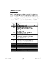
Page 9: ...ee basic setting 1 5 If the power supply is disconnected after detecting the fault the information is deleted and fault code 000 appears on executing test programme 4 If a fault has been detected but the cause of the fault no longer exists temporary fault because the temperature has dropped or the cooking thermometer has been disconnected from the socket the relevant fault code is stored in the me...

Page 10: ...y is the EEPROM control fault F Fault code Type of fault 000 No fault 001 Food thermometer open circuit Ω 002 Fodd thermometer short circuit Ω 003 Appers when an attempt is made to switch on the appliance again in spite of fault code display 002 odr 003 Fault in safety circuit 004 Appers when the child safety system is to be switched on but the circuit is faulty 005 Not used 006 The temperature me...

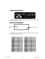
Page 11: ... are tested Programme 6 see basic setting 1 5 This programme displays the temperature measured by the thermostat on the control unit in hexadecimal code see tables HEX Control unit thermostat HEX Control unit thermostat 001 30 034 52 002 25 03C 55 003 15 045 60 004 10 04 E 65 006 5 058 70 007 0 062 75 009 5 06C 80 00B 10 076 85 00E 15 080 90 012 20 08A 95 016 25 093 100 01A 30 09C 105 020 35 0A4 1...

Page 12: ...amme 4 for fault finding Replace power board Disconnect mains and run test programme 4 for fault finding Replace power board 005 Code not used 006 Switch on test programme 2 for testing the relays as the overtemperature can be caused by the relay contacts of a heater supply relay sticking Possibly replace power board Possibly replace power board 007 Replace oven sensor Replace display board 008 Sw...

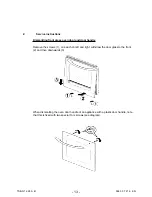
Page 13: ...ss oven door and door handle Remove the screws 1 one each on left and right withdraw the door glass to the front 2 and then downwards 3 When dismantling the oven door handle of an appliance with a plastic door handle note that this is fixed with two special Torx screws see diagram ...

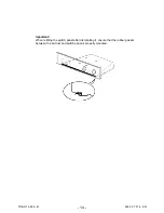
Page 14: ... 14 TSE N 12 99 A B 599 50 72 16 EN Important When refitting the switch panel after dismantling it ensure that the rubber gasket between the air duct and switch panel is properly mounted ...

Reviews: