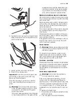
The control of preservation of the flexible pipe
consists in checking that:
• it doesn't show cracks, cuts, marks of
burning both on the end parts and on its
full extent;
• the material is not hardened, but shows its
normal elasticity;
• the fastening clamps are not rusted;
• expiry term is not due. If one or more ab-
normalities are seen, do not repair the
pipe, but replace it.
Important!
Once installation is complete,
check the perfect seal of every pipe fitting,
using a soapy solution, never a flame.
Adaptation to different kinds of gas
To adapt the appliance to a different kind of
gas from the one the appliance has been set
for, follow the instructions below in their or-
der.
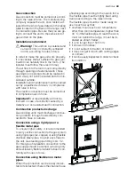
Gas connection :
LPG
: use the rubber pipe holder «D».
Natural gas
: use the pipe holder «E».
Always insert the gasket sealing «B». Then
proceed with the gas connection, as indica-
ted in the relevant paragraphs.
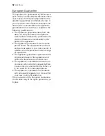
Hob burners nozzles
Nozzles replacement
1. Remove the pan supports.
2. Extract the caps and the wall baffles of
the burners.
3. Using a socket spanner 7 unscrew and
remove the nozzles replacing them with
the ones required for the kind of gas in
use (see table " Burner characteristics " ) .
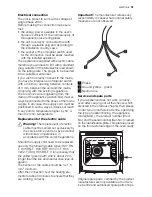
1
Gas connection point
2
Gasket
3
Adjustable connection
4
LPG rubber pipe holder
5
Natural gas pipe holder
4. Reassemble the parts following the same
procedure backwards.
5. Replace the rating label (placed near the
gas supply pipe) with the relevant one for
the new type of gas supply. You can find
this label in the package of the injectors
supplied with the appliance.
These burners do not need any primary air
regulation.
Adjustment of minimum level
To adjust the minimum level of the burners,
proceed as follows:
1. light the burner;
2. turn the knob on the position of minimum
flame;
3. remove the knob;
4. with a thin screwdriver, adjust the by-
pass screw;
If changing from natural gas 20 mbar/13
mbar to liquid gas, completely tighten
the adjustment screw in, until a small
regular flame is obtained.
If changing from liquid gas to natural gas
20 mbar, undo the by-pass screw about
1/4 of a turn, until a small regular flame
is obtained.
If changing from natural gas 20 mbar to
natural gas 13 mbar undo the by-pass
screw about 1/4 of a turn, until a small
regular flame is obtained.
If changing from liquid gas to natural gas
13 mbar, undo the by-pass screw about
3/4 of a turn, until a small regular flame
is obtained.
Reassemble the parts following the same
procedure backwards.
Finally, check the flame does not go out
when quickly turning the knob from the max-
imum position to the minimum position.
50
electrolux
Summary of Contents for EKM60150
Page 53: ...electrolux 53 ...
Page 54: ...54 electrolux ...
Page 55: ...electrolux 55 ...
Page 56: ...359056911 A 10062008 www electrolux com www electrolux ru ...


