Component Teardown
4-9
Door Replacement
1. Disconnect the power supply cord.
2. Push the open button and open the door slightly.
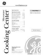
3. Insert a putty knife (thickness of about 0.5mm) into
the gap between the choke cover and door frame as
shown in Figure 4-7 to free engaging parts.
4. Pry the choke cover by inserting a putty knife as
shown Figure 4-7.
5. Release choke cover from door panel.
6. Now choke cover is free.
7. Release two (2) pins of door panel from two (2) holes
of upper and lower oven hinges by lifting up.
8. Now, door panel with door frame is free from oven
cavity.
9. Release the door panel from twelve (12) tabs of door
frame.
10. Remove the door panel from the door frame.
11. Now, door panel with sealer film is free.
12. Tear sealer film from door panel.
13. Now, door panel is free.
14. Slide latch head upward and remove it from door
frame with releasing latch spring from door frame and
latch head.
15. Now, latch head and latch spring are free.
16. Remove door screen from door frame
17. Now, door frame is free.
After adjustment, check the following.
1. In and out play of door remains less than 0.5mm
when in the latched position. First check upper
position of latch hook, pushing and pulling upper
portion of door toward the oven face. Then check
lower portion of the latch hook, pushing and pulling
lower portion of the door toward the oven face. Both
results (play in the door) should be less than 0.5mm.
2. The door sensing switch, primary switch and third
door switch interrupt the circuit before the door can
be opened.
3. Monitor switch contacts close when door is opened.
4. Re-install outer case and check for microwave
leakage around door with an approved microwave
survey meter.
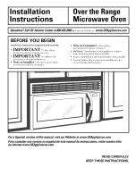
Door Sensing
Switch
Monitor Switch
Switch Lever
Third Door
Switch
Latch Heads
Door
Primary
Switch
Figure 4-6. Door Switch Components
Figure 4-7. Door Components
When carrying out any repair to the door, do not
bend or warp the slit choke (tabs on the door
panel assembly) to prevent microwave leakage.
Choke Cover
Door Frame
Putty Knife
Summary of Contents for EI27MO45GSA
Page 2: ......
Page 32: ...Troubleshooting and Testing 3 14 Notes ...
Page 46: ...Wiring Diagrams 5 4 Notes ...
Page 52: ...Parts List 6 6 Notes ...