background image

14

INSTALLING THE COOKER HOOD

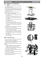
Drilling the Ceiling/Support 
Shelf

•  Use a plumb line to mark the centre of the hob on 

the ceiling/support shelf.

•  Place the drilling template 

21

 provided on the ceiling/

support shelf, making sure that the template is in the 
correct position by lining up the axes of the template 
with those of the hob.

•  Mark the centres of the holes in the template.
•  Drill the holes at the points marked:

•  For concrete ceilings, drill for plugs appropriate to 

the screw size.

•  For hollow brick ceilings with wall thickness of  20 

mm: drill ø 10 mm (immediately insert the Dowels 
not provided).

•  For wooden beam ceilings, drill according to the 

wood screws used.

•  For wooden shelf, drill ø 7 mm.
•  For the power supply cable feed, drill ø 10 mm.
•  For the air outlet (Ducted Version), drill according 

to the diameter of the external air exhaust duct 
connection.

•  Insert two screws of the following type, crossing them 

and leaving 4-5 mm from the ceiling:
•  For concrete ceilings, use the appropriate plugs 

for the screw size (not provided).

•  For Cavity ceiling with inner space, with wall thi-

ckness of approx. 20 mm, Screws not provided.

•  For wooden beam ceilings, use 4 wood screws 

(not provided).

•  For wooden shelf, use 4 screws with washers and 

nuts (not provided) 

Fixing the Frame

•  Loosen the two screws  fastening the lower chimney 

and remove this from the lower fra me.

•  Loosen the two screws  fastening the upper  chimney 

and remove this from the upper fra me.

If you wish to adjust the height of the frame, proceed 
as follows:

• Unfasten the eight metric screws joining the two 

columns, located at the sides of the frame. 

•  Adjust the frame to the height required, then replace 

all the screws removed as above.

•  Insert the upper chimney stack from above, and leave 

it running free on the frame.

•  Lift up the frame, 

fi

 t  the frame slots onto the screws 

up to the slot end positions.

•  Tighten the two screws and fasten the other two 

screws provided with the hood.

2

2

1

1

Summary of Contents for CHI 950

Page 1: ...INSTRUCTION BOOK FOR ELECTROLUX COOKER HOOD CHI 950 cod 436002578_03 060403 UK ...

Page 2: ......

Page 3: ... ownership please ensure you complete and return the guarantee card supplied with the appliance For the User Important Safety Information Your Appliance Operating Instructions Cooker Hood Controls To Operate Recirculation Extraction Maintenance and Cleaning External Cleaning Metal Grease Filters Charcoal Filters To Remove Replace Charcoal Filter Changing the Halogen Light Something Not Working Ser...

Page 4: ...otor has cooled significantly It is dangerous to alter the specifications or modify this product in any way When installed between adjoining wall cabinets the wall cabinets must not overhang the hob If the room where the hood is to be used contains a fuel burning appliance such as a central heating boiler then its flue must be of the room sealed or balanced flue type If other types of flue or appl...

Page 5: ...5 YOUR APPLIANCE ...

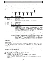
Page 6: ...r filter saturation alarm has been triggered and the filter has to be replaced the metal grease filters must also be washed The activated charcoal odour filter is triggered after 200 working hours Activation and Reset check the Maintenance paragraph To Operate Select the required fan speed and light if required Recirculation In the recirculation mode the contaminated air enters the cooker hood thr...

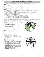
Page 7: ...the control panel Metal Grease Filters The filters are washable and must be cleaned when the Led S1 lights up or at least every 2 months of opera tion or more frequently for particularly heavy usage Remove the metal grease filters one at a time by Releasing the catches on the filters the filters can be removed The metal grease filters should be washed by hand in mild soapy water or in a dishwasher...

Page 8: ...enerated It must be replaced when led S1 flashes or at least every 4 months The alarm signal will only light up when the extractor motor is switched on To Remove Replace the Charcoal Filters Remove the metal grease filters Remove the saturated activated carbon filter by releasing the fixing hooks Fit the new filter by hooking it into its seating Replace the metal grease filters This appliance can ...

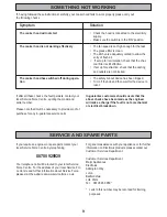
Page 9: ... char coal filter is still effective If set up for extraction check that the ducting and outlets are not blocked The safety cut out device has been tripped Tum off the hob and then wait for the device to reset In guarantee customers should ensure that the above checks have been made as the engineer will make a charge if the fault is not a mechanical or electrical breakdown If you require an engine...

Page 10: ...Costs incurred for calls to put right appliances improperly installed or calls to appliances outside the United Kingdom Appliances found to be in use within a commercial environment plus those which are the subject of rental agree ments Products of Electrolux manufacture which are not marked by Electrolux This guarantee is in addition to your statutory and legal rights ELECTROLUX EUROPEAN GUARANTE...

Page 11: ...upply ensure that the mains voltage corresponds to the voltage on the rating plate inside the cooker hood This appliance is fitted with a 2 core mains cable and must be permanently connected to the electricity supply via a double pole switch having 3mm minimum contact gap on each pole A Switched Fuse Connection Unit to BS1363 Part 4 fitted with a 3 Amp fuse is a recom mended mains supply connectio...

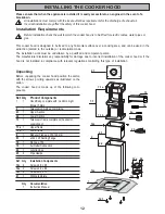
Page 12: ... incorrect installation of the cooker hood or if the hood is not installed in compliance with relevant regulations controlling this type of installation Unpacking Before unpacking the cooker hood position the carton with the arrows pointing upwards as illustrated on the carton The cooker hood is made up of the following com ponents Ref Q ty Product Components 1 1 Hood Body complete with Controls L...

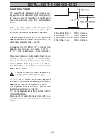
Page 13: ...red when installed above a slot in electric cooker or 787mm 30 1 2 when installed above a slot in gas cooker When installed between adjoining wall cabinets the wall cabinets must not overhang the hob and the distance between the underside of the cabinet and the worktop must be 450mm If the height of the wall cabinet is less than 450mm a gap of 50mm must be maintained either side of the hob This co...

Page 14: ...screws of the following type crossing them and leaving 4 5 mm from the ceiling For concrete ceilings use the appropriate plugs for the screw size not provided For Cavity ceiling with inner space with wall thi ckness of approx 20 mm Screws not provided For wooden beam ceilings use 4 wood screws not provided For wooden shelf use 4 screws with washers and nuts not provided Fixing the Frame Loosen the...

Page 15: ...impaired The ducting used must be manufactured from fire retardent material conforming to the relevant British Standard or DIN 4102 B1 When the cooker hood is ducted to the outside the charcoal filter must be removed INSTALLING THE COOKER HOOD Before tightening the screws completely it is possible to adjust the frame by turning it Make sure that the screws do not come out of their seats in the slo...

Page 16: ...quate supply of air to the room The cooker ducting extraction mode must never be connected to central heating flues radiators or water heaters etc Recirculation The cooker hood is supplied specified for use in the recirculation mode with the charcoal filter fitted In the recirculation mode contaminated air is passed through the charcoal filter to be purified and recirculated into the kitchen throu...

Page 17: ...Before fixing the hood body to the frame Remove the grease filters from the hood body Remove any activated charcoal filters From below use the 4 screws 12f M6 x 10 Electrical Connection Being sure that the connector of the feeding cable is correctly inserted in the socket placed on the side of the fan Connect the control connector Cmd Connect the lights connector Lux Place the connectors in the ju...

Page 18: ...to the Service Force Centre covering your post code area Service and Spare Parts Before calling out an engineer please ensure you have read the details under the heading Something Not Working When you contact the Service Force Centre you will need to give the following details 1 Your name address and post code 2 Your telephone number 3 Clear and concise details of the fault 4 The model and serial ...

Page 19: ......

Page 20: ...AddingtonWay Luton BEDFORDSHIRE LU4 9QQ Electrolux plc 2002 ...

Reviews: