

6.
4
6.
3
7
XBM10 GB 06 2015
6.3 DISMANTLING THE PLANETARY ASSEMBLY
• Proceed as follows:
- Remove the cover with the rear screw, raising it slightly and
pushing it forwards so as to gain access to the transmission
and disconnect the electrical harness.
- Put the lever to the min. speed position (No. 1).
- Then put the lever to the max. speed position (No. 8).
- Disengage the belt from the driven pulley.
- Hold the belt on the side and pull towards you until it releases
from the variable drive pulley.
- Unscrew the driven pulley nut. (19 mm Hex spanner).
- Remove the driven pulley.
- Tap the end of the shaft with a mallet to lower the planetary
gear output shaft assembly.
Support the planetary gear assembly to avoid it falling.
• Clean the mixer and grease the gears and crownwheel with
special food compatible grease (ask us).
• Fit the planetary gear, tighten the screw of the driven pulley
and tension the belt (see § 6.2).
• Run the mixer at low speed for a short while to distribute the
grease evenly then increase the speed.
6.4 SPEED SELECTION
In normal operation, on changing from high speed to low speed,
the lever moves back slightly before holding in position.
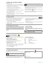
• If it does not stabilise, make the following adjustment:
- Run the beater at low speed (1) and then stop it.
- Unscrew the speed change lever.
- Remove the cover to gain access to the mechanism and
retighten the lever.
- Release the lock-nut on the backstop screw A.
- Start the beater up again and loosen the backstop screw until
the lever is held at all speeds.
- Tighten the lock-nut.
- he beaters are factory-set to run at approximately 38 to 180
rpm (planetary gear speed).
6.5 CHECKING THE SAFETY DEVICE
• The proper operation of the safety device must be checked
before each time the machine is used. The motor must stop
in less than 4 seconds on opening the safety guard 30 mm
at the front between the bowl and the guard and on lowering
the bowl.
• If this does not happen:
- Do not use the machine.
- Have it adjusted by the service department of your local
dealer.
6.6 ELECTRICAL COMPONENTS
See electrical diagrams.
• Check the condition of the power cable and the electrical
components regularly.
• Access to electrical components:
- Unplug and put the machine on its back.
- Remove the base plate (4 screws – 8 mm spanner).
• Identification of the motor wires:
- Power circuit: black
- Motor:
A
: red -
B
: green -
C
: yellow -
D
: white -
E
: blue -
F
:
black –
G
: orange –
H
: violet –
I
: grey –
J
: brown –
K
: pink.
- Phases:
L
Single phase; - Neutral:
N
- Earth: Green/Yellow
B/C
• Component identification:
S1
:
Guard safety device
S2
:
Motor sensor
S3
:
Bowl presence safety device
M
:
Motor
CC
:
Control board
CPU :
Electrical power board
6.7 ADDRES SFOR MAINTENANCE
We recommend that you contact first the seller of the machine
first of all.
For all requests for information or orders for spare parts,
quote the type of machine, the serial number and the
electrical specifications.
The manufacturer reserves the right to modify and make impro-
vements to the products without giving prior warning.
Supplier’s stamp
Date of purchase: ...............................................
The machine must not operate if the bowl is not
in position on the cradle.


