Electro Industries Mini-Boiler EMB-S-1 Installation & Operating Instructions Manual Download Page 3


03/12/2019  

1


BI309 

GENERAL


As stated, this product series applies to under floor hydronic heating.  The basic 

components

 for an electric 

energy heating system typically include: 
 
1.


Electric Mini-Boiler itself – covered by this manual. 

2.


Thermostat hookup control – covered by this manual. 

3.


Plumbing kit or piping material at the boiler itself – can be ordered as a kit, reference catalog number EMB-PK. 

a.


These items are shown on plumbing installation drawing BX305. 

4.


Circulating pump – typically sized for head pressure and system flow requirement, typical catalog number EMB-P2.  

5.


The under floor circulating tubes and manifolds – provided and manufactured by others, not covered in this manual. 


APPROVED TUBING/PIPING 


When plumbing this boiler and its peripheral parts to the loop system, all plumbing parts and/or tubing must be 
sealed to prevent entrance of oxygen. 


Use only tubing or polyethylene tubing with oxygen Diffusion Barrier (ie. PEX). 


SYSTEM OR WATER FLOW 


In order to prevent rapid stage cycling and long term deterioration of components and elements, it is important 
the water flow be greater than the specified 0.3 GPM per kW. 
 

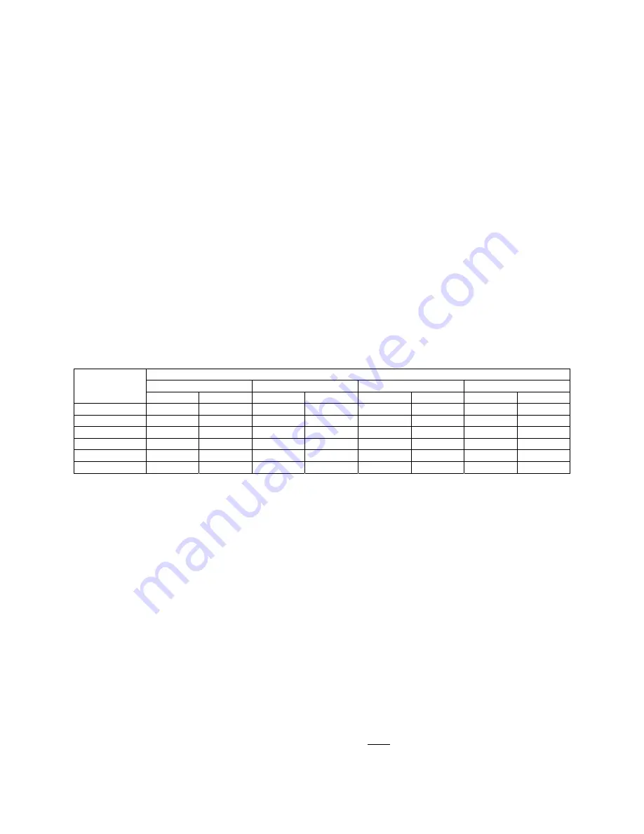
WATER FLOW REQUIREMENTS 

(MINIMUM 0.3 GPM PER KW WATER FLOW THROUGH BOILER)


Model


Water Temperature Rise 

Flow – 10° F/6° C 

Head Loss 

Flow – 20° F/11° C 

Head Loss 

gpm lpm  ft  m  gpm lpm  ft  m 

EMB-S-1 .75 2.83 .01 .003  .37  1.39 .003 .001 
EMB-S-2 1.7 6.43 .01 .006 .85 3.21 .02 .006 
EMB-S-4 3.41 12.88 .08  .024 1.70 6.42  .04  .012 
EMB-S-5 3.07 11.60 .06  .018 1.53 5.78  .02  .006 
EMB-S-7 4.78 18.06 .12  .036 2.39 9.03  .06  .01 
EMB-S-9 6.14 23.20 .23  .07 3.07 11.60 .10  .03 


Note: Head Loss based on 110° F return temperature. 


TEMPERATURE SENSING STAGING CONTROL 


This model series is factory equipped with a digital supply water sensor and a staging controller.  The controller 
regulates the elements to maintain a preset maximum or preset operating temperature.  The control board has a 
front panel screwdriver adjustment (see Operational Tips section) for setting the operating temperature point. 
 
During initial turn on (slab stat call for heat) there is an initial pump on in attempt to stabilize the loop 
temperature followed by stage 1.  After approximately 4 minutes if the water supply sensor value is still below 
the set point, stage 2 is turned on.  At this point, the water temperature is sampled every 4 minutes to determine 
correct element sequence.  Assuming proper flow, the element power will regulate to maintain this preset 
temperature. 
 

ROOM THERMOSTAT PLACEMENT 


Comfort and proper space heating response is a direct relationship to the room thermostat type and the 
placement of the thermostat sensing bulb.  Typically an under floor heating system can be broken down into two 
categories. 


Energy storage, water tubing is under the concrete or within the sand base

 - The controlling 

thermostat must have a remote bulb, and this remote bulb must sense the concrete slab temperature (slab 
stat).  Coordinated with the concrete pour, install a ¾” PVC, minimum bend radius of 7 inches, and 
locate at approximately center (vertical) of the concrete slab.  The thermostat sensing bulb can later be 

Summary of Contents for Mini-Boiler EMB-S-1

Page 1: ...g systems This model includes factory installed temperature sensing staging Comment If this application is for traditional hydronic heating requiring temperatures greater than 160 F and capacities larger than shown above contact factory for other Electro Boiler product series In this approximate sizing the EB M model series is fully modulating and designed for temperatures up to 180 F The EB M and...

Page 2: ...g Staging Control 1 Room Thermostat Placement 1 Built In Temperature Control 2 Water Flow Calculation 2 Installation Requirements 2 Electric Supply 3 Clearances 3 Mechanical Installation 4 Electrical Hookup 5 Water Fill Procedure 6 Operational Tips 8 Troubleshooting Helps 9 Drawings BX305 BH310 UAW411 BL001 XX017 ...

Page 3: ...MB S 5 3 07 11 60 06 018 1 53 5 78 02 006 EMB S 7 4 78 18 06 12 036 2 39 9 03 06 01 EMB S 9 6 14 23 20 23 07 3 07 11 60 10 03 Note Head Loss based on 110 F return temperature TEMPERATURE SENSING STAGING CONTROL This model series is factory equipped with a digital supply water sensor and a staging controller The controller regulates the elements to maintain a preset maximum or preset operating temp...

Page 4: ...at least 15 minutes GPM Volts x Amps x 3 4 Example 240 volts x 36 amps x 3 4 29376 5 8 gpm 500 x Temp rise 500 x 10 degree rise 5000 INFORMATION WATER FLOW CALCULATIONS METRIC L min Volts x Amps x 3 587 Example 240 volts x 36 amps x 3 587 30991 68 20 57 L min 251 04 x Temp rise C 251 04 x 6 C rise 1506 24 INSTALLATION REQUIREMENTS 1 All installation work must be performed by trained qualified cont...

Page 5: ...actices for handling electrical sheet metal and material handling processes Use them ELECTRIC SUPPLY Model Volts Phase Watts Btu h Amps CB Element Stg 1 Stg 2 EMB S 1 120 1 60 Hz 1 100 3 753 9 2 1 EMB S 2 120 1 60 Hz 2 500 8 530 20 8 1 EMB S 4 120 1 60 Hz 5 000 17 060 41 7 1 1 EMB S 5 240 208 1 60 Hz 4 500 3 500 15 354 11 942 18 8 16 8 30A 1 EMB S 7 240 208 1 60 Hz 7 000 5 300 23 885 17 913 29 2 2...

Page 6: ... required This can be an air diaphragm tank as provided in the plumbing kit or a basic empty tank where air is compressed at the tank top Temperature Pressure Gauge Recommended to observe the operation of the system Actually a temperature gauge at the inlet and outlet is desirable Pressure Safety Valve This is required at the hot outlet and is furnished as a loose component with the boiler unit it...

Page 7: ...NNECTION TO THE CIRCUIT BREAKER TERMINALS AND INSIDE THIS PRODUCT S CABINET WARNING TO AVOID THE RISK OF ELECTRIC SHOCK OR DEATH WIRING TO THE UNIT MUST BE PROPERLY GROUNDED FAILURE TO PROPERLY GROUND THE UNIT CAN RESULT IN A HAZARD LEADING TO PERSONAL INJURY OR DEATH NOTE This model series is designed and equipped for 240 volt residential single phase If this unit is used on 208 volt energy capac...

Page 8: ...S 1 Unless the source water is unusually poor and or rust elements additives are not required It is recommended the water source as shown on drawing BX305 comes through the household water softener 2 Impurities within a closed loop hydronic boiler are considerably less damaging than the typical domestic water heater In a closed loop electric boiler the water impurities boil out and the system esse...

Page 9: ...he metal pipe and listen for air bubbles If the water flow is consistent and quiet the system is probably purged and water filled 9 Close the drain valve Open the inlet gate valve 10 The cold system pressure at the gauge should be approximately 10 to 14 PSI 11 Close water supply valve and disconnect water supply 12 Optional The circulating pump can be energized during this fill operation by having...

Page 10: ...W input or interrupted by the load control device even though there is a W input This diagram illustrates this pin jumper arrangement This unit is factory setup in the W position meaning the pump will always run as a direct function of R to W operating thermostat By simply moving this black 2 position jumper to the L the pump will be turned off during load control interrupt 8 At outlet temperature...

Page 11: ...same as a blown fuse no front panel boiler power green LED To reset this device simple press the red button Comment The hi limit auto reset red LED is only operational during an active heat call lower red LED on WARMFLO TEMPERATURE BYPASS TROUBLESHOOTING OR TESTING Adding a jumper between W screw terminal and tab marked E bypasses the temperature sensing and WarmFlo control In other words with the...

Page 12: ...EMB S H 12 04 18 1 of 2 BX305 ...

Page 13: ...EMB S H 12 04 18 2 of 2 BX305 ...

Page 14: ...EMB S EMB H 03 19 19 1 of 2 BH310 G ...

Page 15: ...EMB S EMB H 03 19 19 2 of 2 BH310 G ...

Page 16: ...DECAL TITLEBLOCK ...

Page 17: ...itional 4 enclosure and 40VA transformer Pumps EB ZEA8 with enclosure and 40VA transformer for 8 zone pumps Zone Valves EB ZTS 1 install within boiler cabinet encl option EB ZTS 2 add additional 4 enclosure and 40VA transformer EB ZES8 with enclosure no transformer for 8 zone valves ZONE CONTROLLER SWITCHING RELAY EE 5051 MULTI BOILER EB C STG5 This DPDT 24 volt switching relay provides a convenie...

Page 18: ...erature pressure gauge pressure relief safety valve and when applicable the WarmFloTM electronic control sensors These kits provide the additional components for easy installation 5585 Mini Boiler 10 kW TS Series 5586 TS Series Standard 5578 3 4 Pipe 5582 1 Pipe 5579 1 1 4 Pipe 120V 1 25 HP maintenance free wet rotor circulator Pump curve example 5 GPM 19 L 11 ft of head 32 9 kPa 120V 1 6 HP maint...

Page 19: ...acement Labor Allowance Schedule for a period of ninety 90 days from the date of original purchase to the original owner at the original installation site The Repair Replacement Labor Allowance is designed to reduce the cost of repairs This Repair Replacement Labor Allowance may not cover the entire labor fee charged by your dealer contractor TWENTY YEAR 20 LIMITED WARRANTY ON BOILER ELEMENTS AND ...

Page 20: ...ubject to adjustment upon verification of defect 2 Any product or product part that has been damaged as a result of being improperly serviced or operated including but not limited to the following operated during construction phase with insufficient water or air flow allowed to freeze subjected to flood conditions subjected to improper voltages or power supplies operated with air flow or water con...

Reviews: