


ELECTRO FREEZE Soft Serve Model 30RMT
22
184955
123456789012345
123456789012345
123456789012345
123456789012345
123456789012345
123456789012345
123456789012345
123456789012345
123456789012345
123456789012345
123456789012345
123456789012345
123456789012345
123456789012345
123456789012345
123456789012345
123456789012345
123456789012345
123456789012345
123456789012345
123456789012345
123456789012345
123456789012345
123456789012345
123456789012345
123456789012345
123456789012345
123456789012345
123456789012345
123456789012345
123456789012345
123456789012345
123456789012345
123456789012345
123456789012345
123456789012345
123456789012345
123456789012345
123456789012345
123456789012345
123456789012345
123456789012345
123456789012345
123456789012345
123456789012345
123456789012345
123456789012345
123456789012345
123456789012345
123456789012345
123456789012345
123456789012345
123456789012345
123456789012345
123456789012345
123456789012345
123456789012345
123456789012345
123456789012345
123456789012345
123456789012345
123456789012345
123456789012345
123456789012345
123456789012345
123456789012345
123456789012345
123456789012345
123456789012345
123456789012345
123456789012345
123456789012345
123456789012345
123456789012345
123456789012345
123456789012345
123456789012345
123456789012345
123456789012345
123456789012345
123456789012345
123456789012345
123456789012345
123456789012345
123456789012345
123456789012345
123456789012345
123456789012345
123456789012345
123456789012345
123456789012345
123456789012345
123456789012345
123456789012345
123456789012345
123456789012345
123456789012345
123456789012345
123456789012345
123456789012345
123456789012345
123456789012345
123456789012345
123456789012345
123456789012345
123456789012345
123456789012345
123456789012345
123456789012345
123456789012345
123456789012345
123456789012345
123456789012345
123456789012345
123456789012345
123456789012345
123456789012345
123456789012345
123456789012345
123456789012345
123456789012345
123456789012345
123456789012345
123456789012345
123456789012345
123456789012345
123456789012345
123456789012345
123456789012345
123456789012345
123456789012345
123456789012345
123456789012345
123456789012345
123456789012345
123456789012345
123456789012345
123456789012345
123456789012345
123456789012345
123456789012345
123456789012345
123456789012345
123456789012345
123456789012345
123456789012345
123456789012345
123456789012345
123456789012345
123456789012345
123456789012345
123456789012345
123456789012345
123456789012345
123456789012345
123456789012345
123456789012345
123456789012345
123456789012345
123456789012345
123456789012345
123456789012345
123456789012345
123456789012345
123456789012345
123456789012345
123456789012345
123456789012345
123456789012345
123456789012345
123456789012345
123456789012345
123456789012345
123456789012345
123456789012345
123456789012345
123456789012345
123456789012345
123456789012345
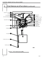
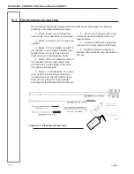
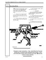
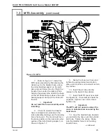
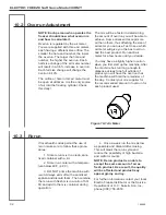
Figure 7-3 Scraper Blade Installation
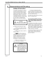
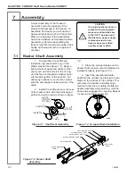
Correct assembly of the freezer is
essential to prevent leakage of the
product and damage to the freezer. To
assemble the freezer you will need an
approved lubricant (such as Petrol-Gel).
Make sure all parts of the assemblies
have been washed and sanitized before
assembling. Persons assembling the
freezer must first wash and sanitize their
hands and forearms with an approved
sanitizer.
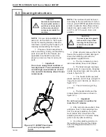
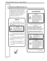
CAUTION
To avoid electrical shock or
contact with moving parts,
make sure all switches are
in the “OFF” position and
that the main power supply
is disconnected. Some
freezers have more than
one disconnect switch.
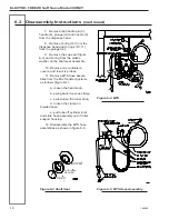
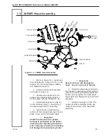
7 Assembly
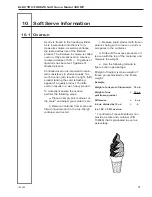
7.1 Beater Shaft Assembly
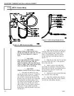
1. To assemble the shaft seal,
install the cup seal and O-ring on the
plastic washer (see figure 7-1). Apply a
light amount of approved sanitary lubri-
cant (such as Petrol-Gel) to the O-ring
and the face of the plastic washer oppo-
site the bell portion of the seal. Do not
allow any lubricant to come into contact
with the bell-shaped rubber portion of the
seals.
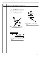
2. Install the shaft seal over the rear
of the beater shaft, with the bell-shaped
portion facing the rear as shown in figure
Figure 7-1 Shaft Seal Assembly
7-2.
3. Place the scraper blades on the
beater shaft, making sure the blades are
installed properly (see figure 7-3).
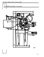
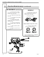
4. Insert the assembled beater
shaft into the cylinder by placing the rear
blade on the bottom of the cylinder. This
will center the beater and allow align-
ment with the drive coupling. Rotate the
beater assembly while pushing, until the
shank has engaged the coupling. Repeat
for second cylinder assembly.
SEAL-ASSY
SHAFT
Figure 7-2 Beater Shaft
Assembly
SEAL-BEATER SHAFT
WASHER-SHAFT SEAL
O-RING-SHAFT SEAL
BLADE-SCRAPER REAR
SHAFT-BEATER
BLADE-SCRAPER
FRONT
O-RING
WASHER
CUP SEAL
LUBRICATE
LUBRICATE
DO NOT
LUBRICATE
CUP SEAL


