
59
© 2006, Elektro-Automatik GmbH & Co. KG
EN
Using the power supply
8. Interface cards
8.1 General
The power supply supports various interface cards for
communication (or analogue control, with IF-A1). All cards
are galvanically isolated up to 2000V.
The digital interface cards IF-R1 (RS232), IF-C1(CAN) and
IF-U1(USB) use a uniform communication protocol. Up to
30 units can be controlled from a PC at once with these cards.
On request: IF-G1 (IEEE 488), IF-AIF (galvanically isolated,
analogue interface with configurable in- and outputs, not
controllable by a PC, only analogue control).
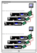
In the addendum the are figures that graphically explain the
use of the various interface cards and suggest some of the
applications which can be realised with them.
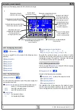
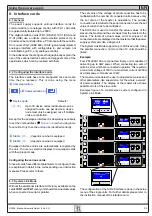
8.2 Configuring the interface cards
The interface cards have to be configured once and each
time they’re replaced. This is done using the menu
Communication
.
M
+
Communi
Device node
Default:
1
= {1..30}
Up to 30 device nodes (addresses) can be
assigned to units, one per device. A device
node must only be assigned once if multiple
units are controlled.
Except for the analogue interface it is absolutely necessary
to set the unit’s address (
Device node
) when using inter-
face cards. Only then the unit can be identified correctly.
Slot A:
{ IF-… }
depends on what is equipped
Slot B:
{ IF-… }
depends on what is equipped
Equipped interface cards are automatically recognized by
the unit. The menu selection displays the equipped cards
with their product code.
Configuring the various cards
Since all cards have different parameters to configure, these
are explained in detail in the corresponding user instruction
manuals. Please refer to them.
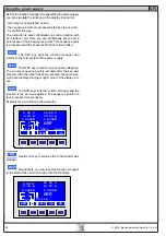
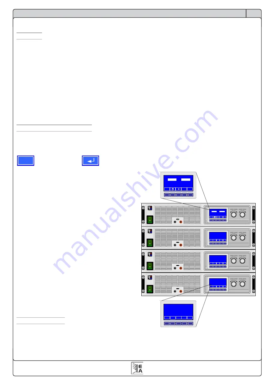
8.3 System Link Mode
Without the additional interface SIO2 (only available on the
cards
IF-R1
and
IF-U1
) every unit shows its own actual values
when connected in serial or parallel.
The set value of the voltage at serial connection has to be
multiplied with the number of connected units, because only
the set value of the master is adjustable. The parallel
connection acts similiar to the serial connection, here the set
value of current has to be multiplied.
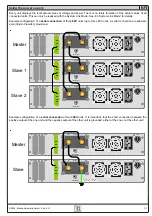
The SIO2 link is used to transfer the actual values of the
slave to the master and the set values from the master to the
slaves. The totals of actual values and set values of all
connected units are displayed on the master so that the power
supply system acts like a single unit.
The System Link Mode supports up to 30 linked units. Using
the parallel connection, not more than 10 units should be
linked.
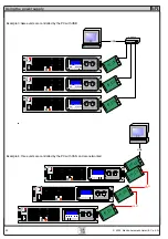
Example:
Four PSI 9080-100 are connected. Every unit is capable of
delivering up to 3kW power. When connecting two sets of
units in serial, which are connected in parallel, this results in
a maximum voltage of 160V or a maximum current of 200A
at a total power of maximum 12kW.
The master unit enables the user to adjust all set values and
other parameters, like supervision, for the whole „network“
of power supplies. The display of the master also shows
possible errors of the slave units.
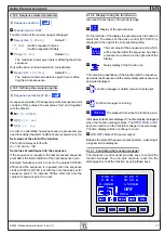
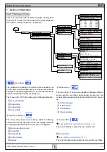
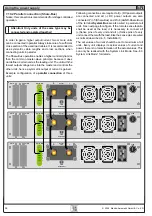
Example figure of a master-slave system configured in
System Link Mode:
The configuration of the SIO2 interface is done in the setup
menu of the single units. For further details please refer to
the instruction manual of the interface card.
Voltage
Settings
Current
Power
Output max. 10 A
POWER SUPPLY
EA-PSI 9080-50
0..80V/0...50A
1500W
+
-
Voltage
Settings
Current
Power
Modul (1,2)
Output max. 10 A
POWER SUPPLY
EA-PSI 9080-50
0..80V/0...50A
1500W
+
-
controlled by master
ONLINE
Voltage
Settings
Current
Power
Modul (2,1)
Output max. 10 A
POWER SUPPLY
EA-PSI 9080-50
0..80V/0...50A
1500W
+
-
controlled by master
ONLINE
Voltage
Settings
Current
Power
Modul (2,2)
Output max. 10 A
POWER SUPPLY
EA-PSI 9080-50
0..80V/0...50A
1500W
+
-
controlled by master
ONLINE
M
ON
P
91.00
140.00 V
120.1
120.0 A
10.93kW
12.00kW
ON
CC
A
p2
V
s2
ON
ON
ON
M
ON
P
91.00
140.00 V
120.1
120.0 A
10.93kW
12.00kW
ON
CC
A
p2
V
s2
Modul (2,2)
controlled by master
ONLINE
ON