


42
© 2006, Elektro-Automatik GmbH & Co. KG
Irrtümer und Änderungen vorbehalten
EN
© 2006, Elektro-Automatik GmbH & Co. KG
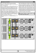
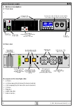
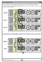
5.6 Interface card slots
The unit can be equipped with two optional interface cards.
The slots to insert the cards are located at the rear side.
The combination of different cards is possible, but not any
card can be combined to any other. For instance, the cards
IF-U1 and IF-R1 must not be equipped at the same time, as
well as two cards of the same type.
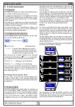
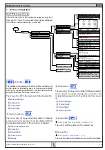
6. Handling explained in detail
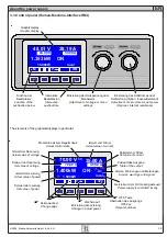
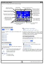
6.1 Switching the unit on
The unit is switched on with the mains switch. After it has
been switched on, the displays shows the device type, the
serial number and, if programmed, a user text.
The user text can be entered via one of the digital interface
cards using an included LabView VI. This text is intended to
identify a single unit in an complex environment of multiple
units.
After the internal system has been verified and has booted,
the last state of the power supply (set values, alarm
management etc.) is restored. The return state of the output
after a mains loss (power fail error) or after the unit was
switched on can be set in the
Profile
menu.
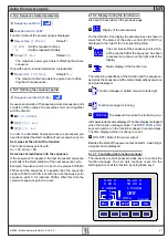
6.2 Switching the power output on
ON
By pressing the
ON
key the power supply output is
switched on. The display shows the current state with „
ON
“.
OFF
The
OFF
key switches the power supply output off
(shutdown). This state is displayed with „
OFF
“.
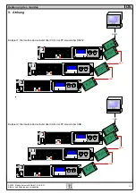
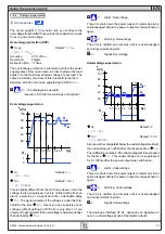
6.3 Adjusting the set values
As long as „
extern
“ or „
remote
“ are not shown in the display,
the set values for voltage, current or power can be set with
the rotary knobs.
Direct setting of the set values
Using the rotary knobs directly sets the set values.
The left rotary knob adjusts the voltage. The set value of the
voltage is displayed invertedly while it is selected and
adjusted.
In the menu there are also options to set upper and lower
adjustment limits
U adj
for the voltage. This can be used
to prevent the user from adjusting higher voltage values than
required and to protect the load.
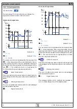
The right rotary knob either sets the set value for the current
or for the power. The set value is displayed invertedly.
With the
SELECT
keys
P
the set values for the power or
I
the set value for the current is
SELECT
ed.
In the menu there are also options to set upper and lower
adjustment limits
I adj
for the current. This can be used to
prevent the user from adjusting higher current values than
required and to protect the load from too high current.
The maximum adjustable power can also be limited.
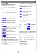
Submitting the set values
Alternatively to the direct adjustment of set values you can
choose to set the set values only after submitting them with
the
RETURN
key. See section „7. Device configuration“ for
details. The set values can still be changed with the rotary
knobs, but are not set in the unit as long as they’re not
submitted. While the set value is unchanged, only its unit is
displayed invertedly. If the set value is changed it is also
displayed invertedly.
The
SELECT
keys switch from current adjustment to power
adjustment for the right rotary knob. The chosen set values
are not submitted to and set by the power supply until then.
Pressing the
RETURN
key submits the set values.
ESC
Pressing the
ESC
key discards the new set values
and the old set values are displayed again.
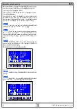
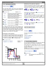
Setting of predefined set values
A table of up to 4 sets of set values is accessible in the menu
Preset List
. One of these sets can be selected to submit
its values.
This key selects the next set of set values. The set
values can then be submitted with the
RETURN
key or
discarded with the
ESC
key. Alternatively, you can select
another set with the rotary knob.
1
3
The chosen set is still 1. After the
RETURN
key
is pressed, the set values of set 3 are submitted to the power
supply. The display then shows the new set values of set 3.
Using the power supply