Elecsys WATCHDOG II MESH Installation And Operation Manual Download Page 12


Watchdog II Mesh User Manual 

P/N 86-0006-00 

Rev E    01-2020 

Page 

12 of 38


F.  Accumulator Channel 

a.  To enable the accumulator input, set switch #6 to the ON position 

b.  To keep the accumulator deactivated, keep switch #6 in the default OFF position. 

G.  Solar Channel 

a.  To monitor the incoming DC voltage from a Solar Panel or a TEG, set switch #7 to the 

ON position. 

b.  If monitoring the incoming DC voltage is not desired, keep switch #7 in the default OFF 

position 


1.5.3 

  Configuring and Linking the Smart Node Channels 


Configuring the Smart Node Channels 

If the Smart Node was ordered as a complete RMU system from Elecsys, the Smart Node channels 
should be configured to the end users application. 
 
If the Smart Node was not configured before it left the factory, the default channel configuration is 
Channel 1 = Voltage (+/- 100V), Channel 2 = Current (+/- 100mV), and Channel 3 = Pipe to Soil (+/- 
10V).  To change the configuration of the Smart Node channels follow steps 1 

– 6 below: 


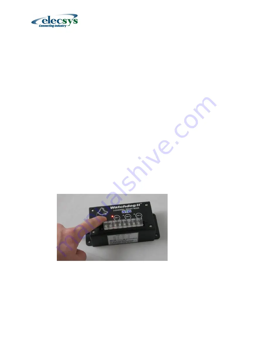
1.  Hold down the Setup Button until the CH 1 LED turns on.  The LED will turn on after 

approximately 3 seconds.  When the LED turns on, release the button.   


2.  All the LEDs will begin to cycle on and off indicating the Smart node is waiting for the 

channel selection.  Push the appropriate channel button for the channel you wish to 
configure.  To exit without changing any of the channels configurations, press and hold the 
Setup Button for approximately 5 seconds. 

 
3.  Once a channel has been selected, the corresponding channel LED will begin to flash every 

3 seconds.  The number of flashes that occurs indicates the current channel configuration. 

1 flash = Voltage Channel (+/-100V) 
2 flashes = Current Channel (+/- 100mV) 
3 flashes = Potential Channel (+/- 10V) 

Summary of Contents for WATCHDOG II MESH

Page 1: ...te System Part Numbers WD2 00 1XXX XX IDP Satellite w o Integrated Enclosure WD2 00 8XXX XX CDMA Cellular w o Integrated Enclosure WD2 00 9XXX XX GSM Cellular w o Integrated Enclosure WD2 16 1XXX XX I...

Page 2: ...Interruption Module if Interruption capability is included 15 1 6 Field Installation Instructions 16 1 6 1 Step 1 Determine the Positive Terminal on the Current Shunt 16 1 6 2 Step 2 Turn off the rec...

Page 3: ...NTG 01 1111 00 01 31 1 13 Smart Node Voltage Measurement Range 31 1 14 Smart Node Current Measurement Range 31 1 15 Smart Node Pipe to Soil Measurement Range 31 1 16 Base Station Analog Input 32 1 16...

Page 4: ...ion based WatchdogCP RMU Systems 1 ea WatchdogCP Mesh RMU P N NTG 01 0003 01 2 ea RMU mounting brackets 1 ea Skywave IDP satellite modem with right angle mounting bracket 1 ea 3 Channel Smart Node Ana...

Page 5: ...tation at a range of 50 feet through a rectifier housing or building walls These wireless sensors represent a major development in the field of CP rectifier monitoring where lightning damage has long...

Page 6: ...DC power input is to be monitored it will occupy one of the 16 measurement channels 1 3 Data Communications The function of the Base Station is to wirelessly collect voltage readings from the wireless...

Page 7: ...network offers global coverage using geostationary satellites spaced around the world over the equator Inmarsat IDP is a two way short data packet service that is ideally suited for remote monitoring...

Page 8: ...r Fail message to the website and will continue to do so every 3 days until its battery is depleted or until power is restored at which point it will transmit a Return to Normal message The RMU can be...

Page 9: ...ilable Continuous power allows real time polling interruption control and reconfiguration Allows more frequent data transmissions Typical continuous current draw at 12 VDC 110 mA cellular system 200 m...

Page 10: ...or 10 stud McMaster Carr 69145K914 10 ea 18 22AWG 3 8 Ring Terminals McMaster Carr 7113K834 10 ea 18 22 AWG In Line Splice McMaster Carr 7227K12 Approximately 12 ea 8 to 11 Wire ties For Interrupter I...

Page 11: ...ered unit leave switch 2 in the default OFF position b For a trickle charge unit using the small solar panel option set switch 2 to ON C Cellular Frequency Setting a If the system is being used in Nor...

Page 12: ...ft the factory the default channel configuration is Channel 1 Voltage 100V Channel 2 Current 100mV and Channel 3 Pipe to Soil 10V To change the configuration of the Smart Node channels follow steps 1...

Page 13: ...NiMH batteries in the Smart Node and replace and secure the protective cover C Open the Base Station and plug the keyed standby battery plug into the connector on the circuit board The unit will start...

Page 14: ...ed LED in Mesh Module turns off If still unsuccessful contact Elecsys Support at 913 825 6366 H When the process for the first channel is complete proceed to the next step to continue linking channels...

Page 15: ...iate rectifier transformer secondary tap power A Remove the 4 screws and the lid of the Interruption Module B Hook up the power cord to a local AC or DC power supply with an output voltage of 12 to 18...

Page 16: ...e the taps that will be used to power the Interrupter Module The Interrupter II may also be powered from 115V or 230V AC 1 6 4 Step 4 Mount Satellite Modem if satellite model was ordered The Skywave s...

Page 17: ...Step 5 Mount the Base Station A Attach the two mounting brackets to the Base Station enclosure using the supplied 10 32 X screws and washers B Mount the RMU brackets to the wooden pole using X 1 lag s...

Page 18: ...quid tight fitting on the bottom of the RMU case and through liquid tight flexible conduit to the circuit breaker panel E Knock out a NPT hole in the circuit breaker box and install a straight or righ...

Page 19: ...er Option 10 to 35 volts DC Use this option to power the RMU from the DC output of a TEG a large Solar Powered System or a small Solar Powered Trickle Charge system A Set the HI LO Input Voltage selec...

Page 20: ...ll be secured The module is ruggedly packaged but should not be mounted outside exposed to the elements Securing options include a Use 4 screws to secure the module via its mounting flanges b Since th...

Page 21: ...the cable jacket as required and strip 3 8 off the red and black wires d Crimp appropriately sized ring terminals to the red and black wires e Connect the red lead to the rectifier output and the blac...

Page 22: ...E The polarity is important The Red lead must be connected to the positive terminal Improper connection will cause erroneous readings If the Smart Node is installed in an integrated enclosure outside...

Page 23: ...rt of the rectifier B Insert the connector end of the GPS antenna and string it through the rectifier Install a grommet through the metal mesh or wrap electrical tape around the small cable to protect...

Page 24: ...e Base Station for 1 second This will begin a PUSHBUTTON TEST that does a complete system test It identifies the strength of the satellite or cell phone signal checks for proper module linkage sends v...

Page 25: ...y contact with the system will come by using the website For this reason Elecsys has put a lot of thought into making the website simple and intuitive for CP technicians to use Key considerations were...

Page 26: ...tude and Longitude must be properly entered before the satellite photo map of the site can be displayed on the Site Page Time Zone Select the Time Zone of the Site CP Group Select the CP Group which p...

Page 27: ...volts Default Lower 5 V Upper 50 V Ch 2 Current Alarm Limit Upper and Lower Alarm limits for Channel 2 generally rectifier amps 0 to 100 Amps Default Lower 2 A Lower 50 A GPS synchronized Interrupter...

Page 28: ...he Reporting Schedule box NOTE If you wish to change the Reporting Period after the unit has been installed you can do so from the website without having to revisit the remote site This is a key featu...

Page 29: ...problem rather than continue the survey and determine after the fact that they have logged bad data C Pushbutton Notification this causes the unit to notify the user with the channel values reported...

Page 30: ...nd select your carrier from the drop down box If your carrier is not listed contact them or do a web search to find the email domain of your cell phone Then enter the email address of your cell phone...

Page 31: ...red 60 VDC 1 13 Smart Node Voltage Measurement Range DC voltage measurement capability 100 to 100 Volts DC Resolution 100 mV DC Measurement accuracy 1 Maximum input voltage 130 Volts DC Input impedanc...

Page 32: ...5 V DC max Measurement accuracy 5 Supply Voltage Range 12 to 14 5V DC Supply Current 600mA 1 17 Base Station Digital Output Supply Current 115mA continuous 800mA pulsed ON Connection RMU Ground Refer...

Page 33: ...roduct will be provided as well as an RMA number A repaired or replacement Product is warranted in accordance with the terms of the standard limited warranty for the balance of the term applicable to...

Page 34: ...2020 Page 34 of 38 1 22 Elecsys Address and Contact Information Products to be returned for warranty or non warranty repair should be sent to Elecsys Inc 846 N Mart Way Court Olathe Kansas 66061 USA 9...

Page 35: ...from defects in workmanship and materials For the same period Elecsys warrants that its products will perform to their specifications and to the extent Elecsys is informed of the use s for which the...

Page 36: ...the external power source to the base station turns off for any reason the base station will generate a report to the web indicating a power fail and then go into its low current sleep mode This comm...

Page 37: ...le is set to 15 days c Alarm Reporting Schedule is set to 5 days d Sample Wakeup Time is set to 4 hours e External Inputs are set to Normally Open switch type f Digital Output is turned off and not li...

Page 38: ...rs 1D Request the Mesh Configuration This command sends the base stations measurement node configuration 1E Update Firmware This command will update the firmware on the base station with the specified...

Reviews: