INSTALLATION
21/56
EN
4 .5
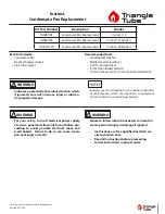
Burner assembly
CAUTION
Install the burner on the boiler according to the installation position shown in “Fig. 12”.
Installation 2,3 and 4 are forbidden for safety reason.
OK
2
1
3
4
Fig. 12
The burner is secured to the boiler using the connection flange supplied with the burner.
Follow the instructions below:
–
couple the gasket (2) supplied with the connection flange (1).
2
1
Fig. 13
CAUTION
Summary of Contents for Firebird FB 4 R LN
Page 55: ......