


factory reset - default parameters loading procedure
Sometime, e.g. when you re-configure an instrument previously used for other works or from other people or
when you have made too many errors during configuration and you decided to re-configure the instrument, it
is possible to restore the factory configuration.
This action allows to put the instrument in a defined condition (the same it was at the first power ON).
The default data are those typical values loaded in the instrument prior to ship it from factory.
To load the factory default parameter set, proceed as follows:
1. Press the
button for more than 5 seconds. The upper display will show
PASS
while the lower display
shows
0
;
2. using
and
buttons set the value
-481
;
3. Push
button;
4. The instrument will turn Off all Leds for a few seconds, then the upper display will show
dFLt
(default) and
then all Leds are turned ON for 2 seconds. at this point the instrument restarts as for a new power ON.
The procedure is complete.
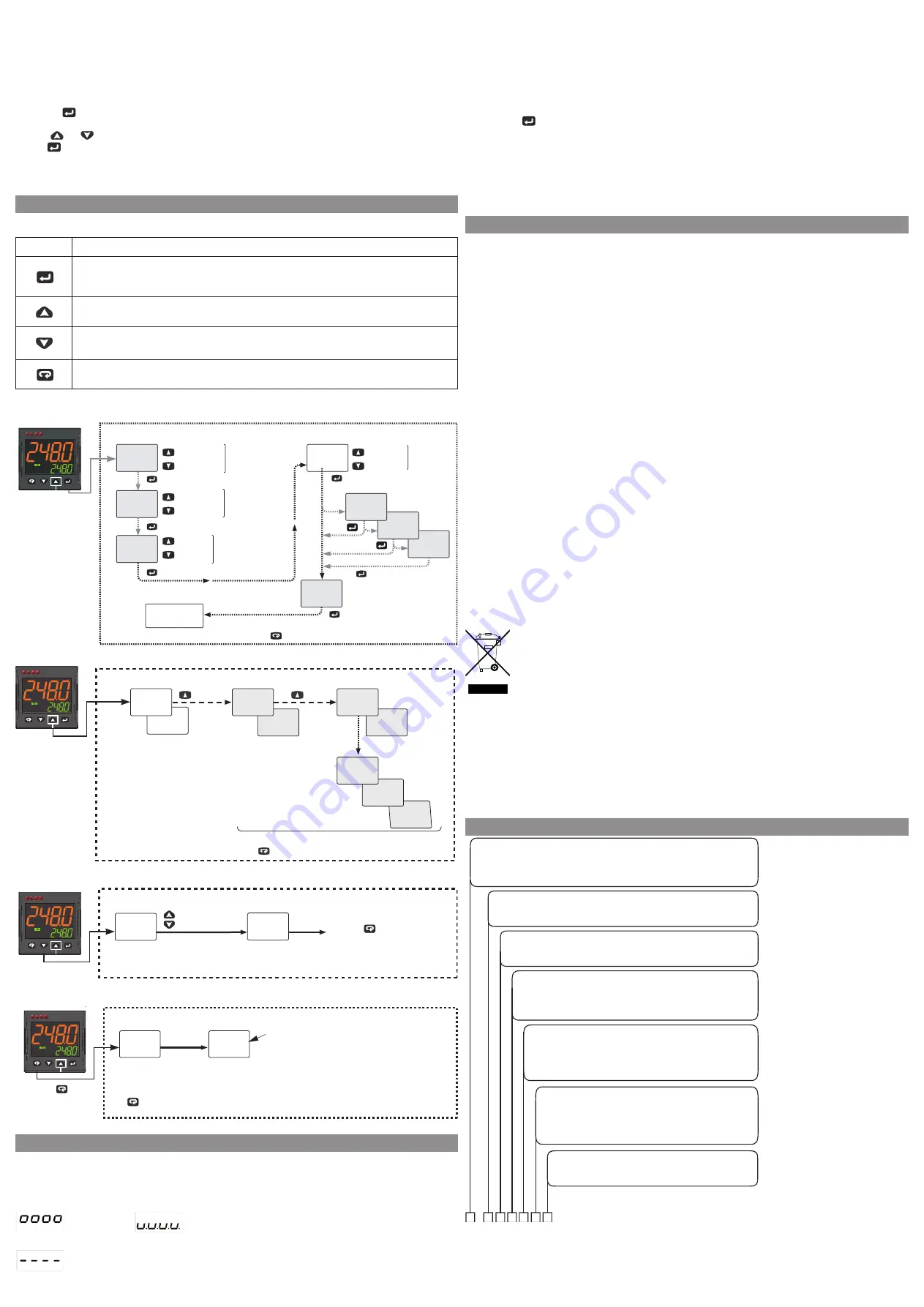
5. OPeraTIVe MOdeS
Keyboard function when the instrument is in auto mode
Key
Operator Mode
access to:
- Operator commands (Timer, Setpoint selection ...)
- Parameters
- configuration
access to Operator additional information (Output value, running time ...)
accesso to Set Point
Start programmed function with
usrb
parameter (autotune, auto/Man, Timer ...)
Operator commands
run
tr.st
248.0
sp
Confirm/Next
Confirm/Next
Confirm/Next
Confirm/Next
Operator Command
Increase
Decrease
run
: Start
hold
: Hold
res
: Reset
Active
Set Point
selection
1
a.sp
If more than
1 Set Point
active
(
nsp
> 1)
Confirm/Next
1
st
SP
value
change
If timer
activated
(
tr.F
)
250
AL1
If AL1 is active
Back to the
first parameter
To return to the Normal Mode, press the key for 3 seconds or wait for the 10s timeout
run
: Start
hold
: Hold
res
: Reset
run
pr.st
Confirm/Next
If program
activated
(
pr.F
)
sp4
nsp
> 1
nsp
> 2
nsp
> 3
340.0
225.0
sp3
120.0
sp2
additional information
t45.2
248.0
h854
248.0
C045
248.0
Additional Information
Output Value %
(e.g. heating = 35%,
cooling = 45%)
Program
Segment
If active
To return to the Normal Mode, press the key for 3 seconds or wait for the 10s timeout
H035
248.0
s1.00
248.0
r1.00
248.0
d854
248.0
U854
248.0
Heating
Cooling
Worked time
(days)
Worked time
(hours)
Power (kW)
or Energy (Wh)
Program/Timer
remaining time
P04.8
248.0
Soak
Ramp
Timer
Program
Set Point change
Press the key (3 s) or wait
for the 10s time out to
store the new Set Point
and return to Normal Mode
Increase value
Decrease value
Operative
Set Point
Changed
operative
Set Point
248.0
sp
250.0
sp
Set Point Change
running the Tuning functions
Press the key
for 3 s
Auto-tune
started
Auto-tune
in progress
tunE
248.0
248.0
248.0.
Note:
The key could be assigned by the user to other functions using the
Usrb parameter
setting
Dot flashes while the Smart TUNE is in progress
Smart TUNE
is a fast and fully automatic procedure that can be
started in any condition, regardless the deviation
from SP. The controller selects automatically the
best tune methodand computes the optimum
PID parameters.
Smart TUNE Start
6. errOr MeSSaGeS
Out of range signals
The instrument points out, on the upper display, the OVer-raNGe and uNder-raNGe conditions using the fol-
lowing indications:
Over-range
under-range
The sensor break will be signalled as an out of range:
Note: When an over-range or an under-range is detected, the alarms operate as in presence of the maximum
or the minimum measurable value respectively.
To check the out of span error condition, proceed as follows:
1. check the input signal source and the connecting line.
2. Make sure that the input signal is in accordance with the instrument configuration.
Otherwise, modify the input configuration (see section 4).
3. If no error is detected, send the instrument to your supplier to be checked.
List of possible errors
eraT fast auto-tune cannot start. The measure value is too close to the set point.
Push the
button in order to delete the error message.
ouLd Overload on output 4. The message shows that a short circuit is present on Out 4 when it is used as ou-
tput or transmitter power supply. When the short circuit disappears the output restarts to operate.
Noat auto-tune not finished within 12 hours.
ereP Possible problem in the instrument memory. The message should automatically disappear, if the error
persists, send the instrument to your supplier.
rone Possible problem of the firmware memory. If this error is detected, send the instrument to your supplier.
errt Possible problem of the calibration memory. If this error is detected, send the instrument to your supplier.
7. GeNeraL NOTeS
Proper use
every possible use not described in this manual must be consider as a improper use.
This instrument is in compliance with
eN 61010-1 “Safety requirements for electrical equipment for measure-
ment, control and laboratory use”; for this reason it could not be used as a safety equipment.
Whenever a failure or a malfunction of the control device may cause dangerous situations for persons, thing
or animals, please remember that the plant has to be equipped with additional safety devices.
eL.cO. S.r.l. and its legal representatives do not assume any responsibility for any damage to people, things
or animals deriving from violation, wrong or improper use or in any case not in compliance with the instru-
ment’s features.
declaration of conformity and Manual retrieval
eLKM43 is a panel mounting, class II instrument. It has been designed with compliance to the european direc-
tives.
all information about the controller use can be found in the engineering user Manual available on the down-
load area of our website www.elco-italy.com .
The declaration of conformity is available for free on request by our web-ticketing support service on our
website.
Maintenance
This instrument does not requires periodical recalibration and it have no consumable parts so that no particular
maintenance is required.
Sometimes it is advisable to clean the instrument.
1. SWITcH THe eQuIPMeNT Off (power supply, relay output, etc.).
2. using a vacuum cleaner or a compressed air jet (max. 3 kg/cm
2
) remove all deposits of dust and dirt which may
be present on the case and on the internal circuits being careful not to damage the electronic components.
3. To clean external plastic or rubber parts use only a cloth moistened with:
z
z
ethyl alcohol (pure or denatured) [c
2
H
5
OH] or
z
z
Isopropyl alcohol (pure or denatured) [(cH
3
)
2
cHOH] or
z
z
Water (H
2
O).
4. Make sure that there are no loose terminals.
5. Before turning ON the instrument make sure it is perfectly dry.
6. apply the power supply to the instrument.
disposal
The appliance (or the product) must be disposed of separately in
compliance with the local standards in force on waste disposal.
Warranty
This product is under warranty against manufacturing defects or faulty materials that are found within 12
months from delivery date. The warranty is limited to repairs or to the replacement of the instrument.
The tampering of the instrument or an improper use of the product will bring about the immediate withdrawal
of the warranty effects.
In the event of a faulty instrument, either within the period of warranty, or further to its expiry, please contact
our our support team through the web-ticketing service on our website.
The return policy will be communicated once the request will be accepted and is also available on the “Sales
condition”.
8. Order cOde
Model
ELKM43
= Controller
ELKM43T
= Cont timer
ELKM43P
= Cont timer + programmer
Power supply
240
= 100... 240 VAC
EV
= 24…240 VAC-VDC
Analogue input + Digital input DI1 (standard)
C
= J, K, R, S, T, PT100, PT 1000 (2 fili), mA, mV, V
E
= J, K, R, S, T, NTC, PTC, mA, mV, V
Output 1
A
= 0/4...20 mA, 0/2...10V
R
= Relais SPST 4A (resistive load)
S
= VDC forSSR
Output 3
-
= Not available
3R
= Relais SPST 2 A (resistive load)
3S
= VDC forSSR
3M
= Relè SPST 2 A (servomotor drive)
Serial communications
-
= TTL Modbus
S
= RS485 TTL Modbus
Output 2
-
= Not available
2R
= Relais SPST 2 A (resistive load)
2S
= VDC for SSR
2M
= Relais SPST 2 A (servomotor drive)
Note: add “W” after the product name for white coloured display led’s
Note: for servomotor drive, both Output 2 and Output 3 codes must be selected as “M”