


no. Par.
description
dec.
Values
default Notes
24 o3ac Out 3 action
0
See O1ac - Out 1 action
dir
25 o4f Out 4 function
0
See O1f - Out 1 function (digital output)
aL
26 o4aL alarms linked up with the out 4
0
See O1aL - alarms linked up with the out 1
aL1 + aL2
27 o4ac Out 4 action
0
See O1ac - Out 1 action
dir
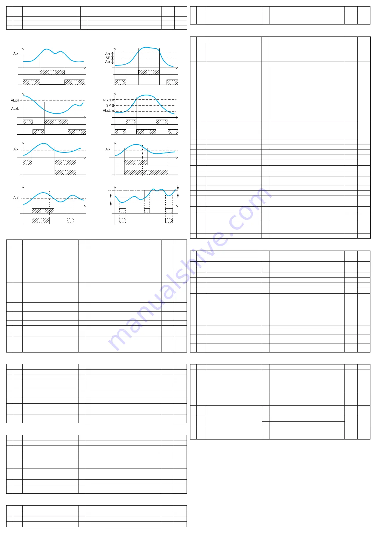
alarm types
ON
ON
ON
ON
ON
ON
ON
ON
ON
ON
ON
ON
ON
ON
ON
ON
ON
PV
PV
PV
Time
PV
External
band
alarm
Internal
band
alarm
Time
Relative band alarm
Deviation
low
alarm
Deviation
High
alarm
Deviation alarm
Absolute band alarm
External
alarm
Iternal
alarm
Time
ON
PV
Alarm not active at power ON
Time
Absolute alarm
Absolute
high
alarm
Absolute
low
alarm
Time
PV
Time
Relative alarm not active at set point change
Ab1 = +1
Ab1 = +0
ON
ON
PV
Latched alarm
Time
Alarm Reset
Alarm Reset
Ab1 = +2
Ab1 = +0
Ab1 = +8
Ab1 = +0
Alarm ACK
Alarm ACK
PWR ON
ON
ON
ON
PV
Acknowledgeable alarm
Time
Ab1 = +4
Ab1 = +0
ON
ON
ON
ON
ON
Sp2
Sp1
ALX
ALX
]
AL1 Group - Alarm 1 parameters
no. Par.
description
dec.
Values
default Notes
28 aL1t alarm 1 type
0
none alarm not used;
Loab absolute low alarm;
Hiab absolute high alarm;
LHao Windows alarm in alarm outside the windows;
LHaI Windows alarm in alarm inside the windows;
Se.br Sensor Break;
Lode deviation low alarm (relative);
Hide deviation high alarm (relative);
LHdo relative band alarm in alarm out of the band;
LHdi
relative band alarm in alarm inside the band.
Hiab
29 ab1 alarm 1 function
0
0... 15:
+1
Not active at power up;
+2
Latched alarm (manual reset);
+4
acknowledgeable alarm;
+8
relative alarm not active at set point change.
0
30 aL1L for High/low alarm, aL1 threshold low limit;
for band alarm, aL1 low alarm threshold dp from -1999 to aL1H (e.u.)
-1999
31 aL1H for High/low alarm, aL1 threshold high limit;
for band alarm, aL1 high alarm threshold dp from aL1L to 9999 (e.u.)
9999
32 aL1 aL1 threshold
dp from aL1L to aL1H (e.u.)
0
33 HaL1 aL1 hysteresis
dp 1... 9999 (e.u.)
1
34 aL1d aL1 delay
0
from 0 (off) to 9999 (s)
off
35 aL1o alarm 1 enabling during Stand-by mode
and out of range conditions
0
0 alarm 1 disabled during Stand by and out of range;
1
alarm 1 enabled in stand by mode;
2
alarm 1 enabled in out of range condition;
3
alarm 1 enabled in stand by and overrange.
0
]
AL2 Group - Alarm 2 parameters
no. Par.
description
dec.
Values
default Notes
36 aL2t alarm 2 type
0
See aL1t
Loab
37 ab2 alarm 2 function
0
See ab1
0
38 aL2L for High/low alarm, aL2 threshold low limit;
for band alarm, aL2 low alarm threshold dp See aL1L
-1999
39 aL2H for High/low alarm, aL2 threshold high limit;
for band alarm, aL2 high alarm threshold dp See aL1H
9999
40 aL2 aL2 threshold
dp See aL1
0
41 HaL2 aL2 hysteresis
dp See HaL1
1
42 aL2d aL2 delay
0
See aL1d
off
43 aL2o alarm 2 enabling during Stand-by mode
and out of range conditions
0
See aL1o
0
]
AL3 Group - Alarm 3 parameters
no. Par.
description
dec.
Values
default Notes
44 aL3t alarm 3 type
0
See aL1t
none
45 ab3 alarm 3 function
0
See ab1
0
46 aL3L for High/low alarm, aL3 threshold low limit;
for band alarm, aL3 low alarm threshold dp See aL1L
-1999
47 aL3H for High/low alarm, aL3 threshold high limit;
for band alarm, aL3 high alarm threshold dp See aL1H
9999
48 aL3 aL3 threshold
dp See aL1
0
49 HaL3 aL3 hysteresis
dp See HaL1
1
50 aL3d aL3 delay
0
See aL1d
off
51 aL3o alarm 3 enabling during Stand-by mode
and out of range conditions
0
See aL1o
0
]
LBA Group - Loop break alarm
no. Par.
description
dec.
Values
default Notes
52 Lbat LBa time
0
from 0 (off) to 9999 (s)
off
53 LbSt delta measure used by LBa during Soft start dP from 0 (off) to 9999 (e.u.)
10
54 LbaS delta measure used by LBa
dP 1...9999 (e.u.)
20
no. Par.
description
dec.
Values
default Notes
55 Lbca condition for LBa enabling
0
uP
active when Pout = 100%;
dn
active when Pout = -100%;
both active in both cases.
both
]
rEG Group - Control parameters
no. Par.
description
dec.
Values
default Notes
56 cont control type
0
Pid
PId (heat and/or);
On.fa ON/Off asymmetric hysteresis;
On.fS ON/Off symmetric hysteresis;
nr
Heat/cool ON/Off control with neutral zone;
3Pt
Servomotor control.
Pid
57 auto autotuning selection
0
-4 Oscillating auto-tune with auto-restart at power ON
and after all point change;
-3 Oscillating auto-tune with manual start;
-2 Oscillating tune with auto-start at first power ON only;
-1 Oscillating auto-tune with auto-restart at all power ON;
0 Not used;
1 fast auto tuning with auto-restart at all power ON;
2 fast auto-tune with auto-start the first power ON only;
3 faST auto-tune with manual start;
4 faST auto-tune with automatic restart at power ON
and after a set point change;
5 Smart-tune with auto-restart at all power ON;
6 Smart-tune with auto-start at first power ON only;
7 Smart-tune with manual start;
8 Smart-tune with auto-restart at power ON and after
a set point change.
7
58 aut.r Manual start of the autotuning
0
off
Not active;
on active.
off
59 SeLf Self tuning enabling
0
no
The instrument does not perform the self-tuning;
YeS The instrument performs the self-tuning.
no
60 HSet Hysteresis of the ON/Off control
dP 0... 9999 (e.u.)
1
61 cPdt Time for compressor protection
0
from 0 (off) to 9999 (s)
off
62 Pb
Proportional band
dP 1... 9999 (e.u.)
50
63 ti
Integral time
0
from 0 (off) to 9999 (s)
200
64 td
derivative time
0
from 0 (off) to 9999 (s)
50
65 fuoc fuzzy overshoot control
2
0.00... 2.00
0.50
66 tcH
Heating output cycle time
1
0.1... 130.0 (s)
20.0
67 rcG
Power ratio between heating and cool-
ing action
2
0.01... 99.99
1.00
68 tcc
cooling output cycle time
1
0.1... 130.0 (s)
20.0
69 rS
Manual reset (Integral pre-load)
1
-100.0... +100.0 (%)
0.0
70 Str.t Servomotor stroke time
0
5...1000 seconds
60
71 db.S Servomotor dead band
0
0...100%
50
72 od
delay at power up
2
from 0.00 (off) to 99.59 (hh.mm)
off
73 St.P Maximum power output used during
soft start
0
-100... 100 (%)
0
74 SSt
Soft start time
2
0.00 (off);
0.01... 7.59 (hh.mm);
inf (always ON).
off
75 SS.tH Threshold for soft start disabling
dP -1999... +9999 (e.u.)
9999
]
SP Group - Set point parameters
no. Par.
description
dec.
Values
default Notes
76 nSP Number of used set points
0
1... 4
1
77 SPLL Minimum set point value
dP from -1999 to SPHL
-1999
78 SPHL Maximum set point value
dP from SPLL to 9999
9999
79 SP
Set point 1
dP from SPLL to SPLH
0
80 SP 2 Set point 2
dP from SPLL to SPLH
0
81 SP 3 Set point 3
dP from SPLL to SPLH
0
82 SP 4 Set point 4
dP from SPLL to SPLH
0
83 a.SP Selection of the active set point
0
from 1 (SP 1) to nSP
1
84 SP.rt remote set point type
0
rSP
The value coming from serial link is used as
remote set point;
trin
The value will be added to the local set point
selected by a.SP and the sum becomes the
operative set point;
Perc
The value will be scaled on the input range
and this value will be used as remote SP.
trin
85 SPLr Local/remote set point selection
0
Loc Local;
ren remote.
Loc
86 SP.u rate of rise for POSITIVe set point change
(ramp uP)
2
0.01... 99.99 (inf) engineering units per minute
inf
87 SP.d rate of rise for NeGaTIVe set point
change (ramp dOWN)
2
0.01... 99.99 (inf) engineering units per minute
inf
]
TIN Group - Timer function parameter
no. Par.
description
dec.
Values
default Notes
88 tr.f Independent timer function
0
None Timer not used;
i.d.a delayed start timer;
i.uP.d delayed start at power up;
i.d.d
feed-through timer;
i.P.L
asymmetrical oscillator with start Off;
i.L.P
asymmetrical oscillator with start ON.
none
89 tr.u Timer unit
0
hh.nn Hours and minutes;
nn.SS Minutes and seconds;
SSS.d Second and tenth of seconds.
nn.SS
90 tr.t1 Time 1
2
When tr.u < 20: 0.01... 99.59
1.00
1
When tr.u = 200: 0.1... 995.9
91 tr.t2 Time 2
2
When tr.u < 2: from 00.00 (off) to 99.59 (inf)
1.00
1
When tr.u = 2: from 000.0 (off) to 995.9 (inf)
92 tr.St Timer status
0
reS
Timer reset;
run
Timer run;
HoLd Timer hold.
reS