


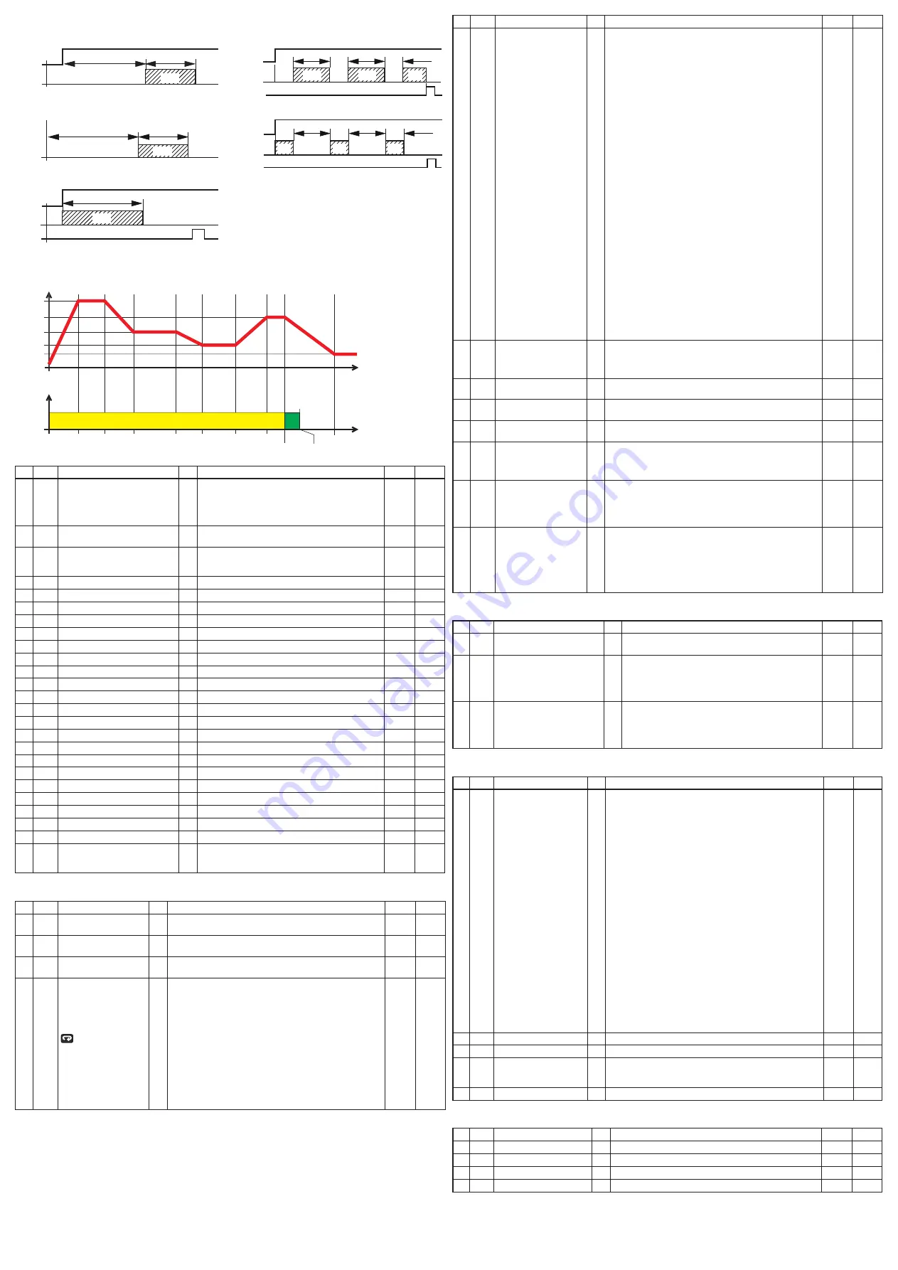
i.d.a
Delayed ON at Start command
i.up.d
Delayed ON at Power ON
i.d.d
At Start command
i.p.l
Asymmetrical oscillator with start in OFF
i.L.p
Asymmetrical oscillator with start in ON
Start
OUT
ON
off
Tr.t1
Tr.t2
off
OUT
PWR ON
ON
off
Tr.t1
Tr.t2
off
Start
OUT
Reset
ON
Tr.t1
off
Start
OUT
Reset
ON
off
Tr.t2
ON
off
Tr.t1
Tr.t1
Tr.t2
ON
off
Tr.t1
Tr.t2
Start
OUT
Reset
ON
off
Tr.t2
off
Tr.t1
Tr.t1
Tr.t2
off
Tr.t1
Tr.t2
ON
ON
PWR ON
PWR ON
Timer Types
(selected by
tr.f
) (option)
]
PRG Group - Programmer function parameters
Time
SPx
Status
Temperature
OFF
Pr.
e
= SPAt
Pr.S1
Pr.S4
Pr.S2
Pr.S3
Prog.
END
prg.1
prt.1
prg.3
prt.3
prg.4
prt.4
prg.2
prt.2
Program RUN
Start
Program Step
no. Par.
description
dec.
Values
default Notes
93 Pr.f
Program action at power up
0
none Programmer not used;
S.uP.d Start at power up with a first step in stand-by;
S.uP.S Start at power up;
u.diG Start at run command detection only;
u.dG.d Start at run command with a first step in stand-by.
none
94 Pr.u Time unit of the soaks
2
hh.nn
Hours and minutes;
nn.SS
Minutes and seconds.
hh.nn
95 Pr.e
Instrument behaviour at the end of
the program execution
0
cnt continue;
SPat
Go to the set point selected by SPat;
St.by
Go to stand-by mode.
SPat
96 Pr.et Time of the end program indication 2
from 0.00 (off) to 99.59 (inf) minutes and seconds off
97 Pr.S1 Set point of the first soak
dP from SPLL to SPHL
0
98 Pr.G1 Gradient of the first ramp
1
0.1... 999.9 engineering unit/minute (inf = Step transfer) inf
99 Pr.t1 Time of the 1
st
soak
2
0.00... 99.59 (time unit of the soaks)
0.10
100 Pr.b1 Wait band of the 1
st
soak
dP 0 (off)/1... 9999 (e.u.)
off
101 Pr.e1 events of the 1
st
group
2
00.00... 11.11 (
0
= event Off;
1
= event ON)
00.00
102 Pr.S2 Set point of the 2
nd
soak
dP Off or from SPLL to SPHL
0
103 Pr.G2 Gradient of the 2
nd
ramp
1
0.1... 999.9 engineering unit/minute (inf = Step transfer) inf
104 Pr.t2 Time of the 2
nd
soak
2
0.00... 99.59 (time unit of the soaks)
0.10
105 Pr.b2 Wait band of the 2
nd
soak
dP 0 (off)/1... 9999 (e.u.)
off
106 Pr.e2 events of the 2
nd
group
2
00.00... 11.11 (
0
= event Off;
1
= event ON)
00.00
107 Pr.S3 Set point of the 3
rd
soak
dP Off or from SPLL to SPHL
0
108 Pr.G3 Gradient of the 3
rd
ramp
1
0.1... 999.9 engineering unit/minute (inf = Step transfer) inf
109 Pr.t3 Time of the 3
rd
soak
2
0.00... 99.59 (time unit of the soaks)
0.10
110 Pr.b3 Wait band of the 3
rd
soak
dP 0 (off)/1... 9999 (e.u.)
off
111 Pr.e3 events of the 3
rd
group
0
00.00... 11.11 (
0
= event Off;
1
= event ON)
00.00
112 Pr.S4 Set point of the 4
th
soak
dP Off or from SPLL to SPHL
0
113 Pr.G4 Gradient of the 4
th
ramp
1
0.1... 999.9 engineering unit/minute (inf = Step transfer) inf
114 Pr.t4 Time of the 4
th
soak
2
0.00... 99.59 (time unit of the soaks)
0.10
115 Pr.b4 Wait band of the 4
th
soak
dP 0 (off)/1... 9999 (e.u.)
off
116 Pr.e4 events of the 4
th
group
0
00.00... 11.11 (
0
= event Off;
1
= event ON)
00.00
117 Pr.St Program status
0
reS
Program reset;
run
Program start;
HoLd
Program hold.
reS
]
PAn Group - Operator HMI
no. Par.
description
dec.
Values
default Notes
118 PaS2 Level 2 password
(limited access level)
0
off (Level 2 not protected by password);
1... 200.
20
119 PaS3 Level 3 password
(complete configuration) 0
3... 200
30
120 PaS4 Level 4 password
(cOde configuration level) 0
201... 400
300
121 uSrb
button function
during ruN TIMe
none No function;
tune
auto-tune/self-tune enabling. a single press (longer than 1
second) starts the auto-tune;
oPLo Manual mode. The first pressure puts the instrument in
manual mode (oPLo) while a second one puts the instrument
in auto mode;
aac
alarm acknowledge;
aSi
alarm reset;
chSP Sequential set point selection;
St.by Stand by mode. The first press puts the instrument in stand by
mode while a second one puts the instrument in auto mode;
Str.t
Timer run/hold/reset;
P.run Program run;
P.reS Program reset;
P.r.H.r Program run/hold/reset.
tune
no. Par.
description
dec.
Values
default Notes
122 diSP display management
none Standard display;
Pou
Power output;
SPf
final set point;
Spo
Operative set point;
aL1
alarm 1 threshold;
aL2
alarm 2 threshold;
aL3
alarm 3 threshold;
Pr.tu - during a soak, the instrument shows the soak elapsed time;
-
during a ramp the display shows the operative set point.
at program end, the instrument alternately displays
P.End
and the measured value;
- When no program is running, the instrument shows the
standard display;
Pr.td
- during a soak, the instrument shows the soak remai-
ning time (count down);
-
during a ramp the display shows the operative set point.
at program end, the instrument alternately displays
P.End
and the measured value;
- When no program is running, the instrument shows the
standard display;
P.t.tu When the programmer is running, the display shows
the total elapsed time. at program end, the instrument
alternately displays
P.End
and the measured value;
P.t.td When the programmer is running, the display shows the total
remaining time (count down). at program end, the instru-
ment alternately displays
P.End
and the measured value;
ti.uP
When the timer is running, the display shows the timer
counting up. at count end, the instrument alternately
displays
t.End
and the measured value;
ti.du
When the timer is running, the display shows the timer
counting down. at count end, the instrument alternately
displays
t.End
and the measured value;
Perc Percent of the power output used during soft start (when the
soft start time is equal to infinite, the limit is always active
and it can also be used when ON/Off control is selected);
PoS
Valve position (servomotor control).
0
123 di.cL display colour
0
The display colour shows the actual deviation (PV - SP);
1
display red (fix);
2
display green (fix);
3
display orange (fix).
0
124 ade
deviation for display colour
management
1... 999 (e.u.)
5
125 di.St display Timeout
2
off (display always ON);
0.1... 99.59 (mm.ss).
off
126 fiLd
filter on the displayed
value
1
off (filter disabled);
from 0.0 (off) to 20.0 (e.u.).
off
128 dSPu Instrument status at power
ON
aS.Pr Starts in the same way it was prior to the power down;
auto Starts in auto mode;
oP.0
Starts in manual mode with power output = 0;
St.bY Starts in stand-by mode.
aS.Pr
129 oPr.e Operative modes enabling
aLL
all modes will be selectable by the next parameter;
au.oP auto and manual (oPLo) mode only will be selectable by
the next parameter;
au.Sb auto and Stand-by modes only will be selectable by the next
parameter
aLL
130 oPer Operative mode selection
If oPr.e = aLL: - auto = auto mode;
- oPLo = Manual mode;
- St.bY = Stand by mode;
If oPr.e = au.oP:
- auto = auto mode;
- oPLo = Manual mode;
If oPr.e = au.Sb:
- auto = auto mode;
- St.bY = Stand by mode.
auto
]
Ser Group - Serial link parameter
no. Par.
description
dec.
Values
default Notes
131 add Instrument address
off;
1... 254.
1
132 baud baud rate
1200 1200 baud;
2400 2400 baud;
9600 9600 baud;
19.2
19200 baud;
38.4
38400 baud.
9600
133 trSP Selection of the value to be
retransmitted (Master)
none retransmission not used (the instrument is a slave);
rSP
The instrument becomes a Master and retransmits the
operative set point;
Perc The instrument become a Master and it retransmits the
power output.
none
]
COn Group - Consumption parameters
no. Par.
description
dec.
Values
default Notes
134 co.tY count type
off Not used;
1
Instantaneous power (kW);
2
Power consumption (kW/h);
3
energy used during program execution. This measure starts
from zero when a program runs end stops at the end of the
program. a new program execution will reset the value;
4
Total worked days: number of hours the instrument is turned
ON divided by 24;
5 Total worked hours: number of hours that the instrument is
turned ON;
6 Total worked days with threshold: number of hours the instru-
ment is turned ON divided by 24, the controller is forced in stand-
by when co.ty value reaches the threshold set in [137] h.Job;
7
Total worked hours with threshold: number of hours that the
instrument is turned ON, the controller is forced in stand-by
when co.ty value reaches the threshold set in [137] h.Job;
8
Totalizer of control relay worked days: number of hours the
control relay has been in ON condition, divided by 24;
9
Totalizer of control relay worked hours: number of hours the
control relay has been in ON condition;
10
Totalizer of control relay worked days with threshold: number
of hours the control relay has been in ON condition divided
by 24, the controller is forced in stand-by when co.ty value
reaches the threshold set in [137] h.Job;
11
Totalizer of control relay worked hours with threshold:
number of hours the control relay has been in ON condition,
the controller is forced in stand-by when co.ty value reaches
the threshold set in [137] h.Job.
off
135 uoLt Nominal Voltage of the load
1... 9999 (V)
230
136 cur
Nominal current of the load
1... 999 (a)
10
137 h.Job Threshold of the working
period
off Threshold not used;
0... 9999 days (when [134] cotY = 4);
0... 9999 hours (when [134] cotY = 5).
0
138 t.Job Worked time (not resettable)
0... 9999 days
]
CAL Group - User calibration group
no. Par.
description
dec.
Values
default Notes
139 aL.P adjust Low Point
from -1999 to (aH.P - 10) in engineering units
0
140 aL.o adjust Low Offset
-300... +300 (e.u.)
0
141 aH.P adjust High Point
from (aL.P + 10) to 9999 engineering units
9999
142 aH.o adjust High Offset
-300... +300
0
Note: To access all the instrument features, please see the “complete configuration procedure” in the “engineering user
Manual”.
complete configuration and Parameter setting can be easily uploaded from the controller and downloaded to
other controllers using the: configuration Key eLcO: KeY a-01.