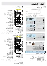
Display board A
Display board B
Display board C
Display board D
1
4
2
3
1
5
Operation mode indicator
(lights up when the compressor is on.)
Timer mode indicator
(Lights up whenTimer operation is selected.)
Power indicator
(Lights up when unit starts.)
T
emp display
Remote signal receiver
(A beeping sound is generated when a signal from remote controller isreceived.)
2
3
4
5
2
3
Signal receiver
1
T
emp.display
2
3
Operation mode indicator
1
10.
12. SWING LEFT/RIGHT button
13.
15. SLEEP button
14. HEALTH button
16.
18. POWER ON/OFF button
20. TEMP button
21.
TIME OFF/ON button
22.
1. Mode display
1
2
3
4
5
9
10
11
12
13
14
15
16
17
8
22
23
24
25
19
20
21
18
7
6
HEALTH
SLEEP
EXTRA
FUNCTION
TIME
OFF
TIME
ON
SWING
Operation mode
AUTO
FAN
COOL DRY
Remote controller
2. Signal sending display
4.FAN SPEED display
5. LOCK display
6. TIME OFF display
TIME ON display
7. TEMP display
3. SWING display
LO
MED
HI
AUTO
Display
circulated
8. Additional functions display
Operation mode
Remote controller
QUIET
TURBO
SLEEP
Supplemented
electrical
heating
HEALTH
9. TURBO button Fan speed reach
the mix value
FAN button
11. COOL button
FAN SPEED button
LOCK button
Control the lightening and extinguishing
of the indoor LED display board.
17. LIGHT button
19. DRY button
SWING UP/DOWN button
23. EXTRA FUNCTION button
24.CANCEL/CONFIRM button
Function: Setting and cancel to the
timer and other additional functions.
25. RESET button
When the remote controller appears
abnormal, use a sharp pointed
article to press this button to reset
the remote.
Healthy function is not available for some units.
TURBO
FAN
2
Parts and Functions
Remote controller
Indoor Unit
Outdoor Unit
4
OUTLET
INLET
CONNECTING PIPING
AND ELECTRICAL WIRING
DRAIN HOSE
4
Function:
HEALTH AIRFLOW
AUTO FAN
---
---
10.
12. SWING LEFT/RIGHT button
13.
15. SLEEP button
14. HEALTH button
16.
18. POWER ON/OFF button
20. TEMP button
21.
TIME OFF/ON
22.
1. Mode display
1
2
3
4
5
9
10
11
12
13
14
15
16
17
8
22
23
24
25
19
20
21
18
7
6
HEALTH
SLEEP
EXTRA
FUNCTION
TIME
OFF
TIME
ON
SWING
Operation mode
AUTO
FAN
HEAT
COOL DRY
Remote controller
2. Signal sending display
4.FAN SPEED display
5. LOCK display
6. TIME OFF display
TIME ON display
7. TEMP display
3. SWING display
LO
MED
HI
AUTO
Display
circulated
8. Additional functions display
Operation mode
Remote controller
QUIET
TURBO
SLEEP
Supplemented
electrical
heating
HEALTH
9. TURBO button Fan speed reach
the mix value
HEAT button
11. COOL button
FAN SPEED button
LOCK button
Control the lightening and extinguishing
of the indoor LED display board.
17. LIGHT button
19. DRY button
button
SWING UP/DOWN button
23. EXTRA FUNCTION button
24.CANCEL/CONFIRM button
Function: Setting and cancel to the
timer and other additional functions.
25. RESET button
When the remote controller appears
abnormal, use a sharp pointed
article to press this button to reset
the remote.
Healthy function is not available for some units.
TURBO
HEAT
Function: HEALTH AIRFLOW
AUTO FAN
---
---
Signal receiver hole
COOL display
HEALTH display
4
2
3
1
5
DRY display
6
T
emp.display
Actual inlet grille may vary from the one shown in the
manual according to the product purchased
2
3
5
6
4
HEAT display
1
(lights up when the compressor is on.)
T
emp
.
display
3
2
4
1
2
3
4
Operation mode indicator
1
TIMER ON/OFF display
TIMER ON OFF display
SLEEP display
Signal receiver hole
Vertical blade
(adjust left and
Display board
right air flow)
Inlet
Air Purifying Filter
(inside)
Emergency
Switch
Horizontal flap
(adjust up and down air flow
Don't adjust it manually)
Outlet
Inlet grille
Cooling capacity test guidance:Step 1,press the button "ON/OFF";
step 2,press the button "COOL";step 3,press the button "TURBO".
Cooling capacity test guidance:Follow remote controller A.
Summary of Contents for ELBA12HAN20
Page 10: ......
Page 11: ......
Page 13: ...40 104 OFF 1 4 2 5 6 3 6...
Page 15: ...1 1 1 o 1 1 o 6 2 1 2 o 1 2 o 3 1 o 3 3 4 4 5 8 3 3 1 2 3 1 2 3...
Page 18: ...1 OFF...


