background image

en│15 

Installation and implementation 


ATTENTION 

Mount and cable the product correctly before connecting the power. 
Possible property damage! 
Do not connect the power supply beforehand! 


Mount the system in accordance with the supplied mounting instructions. 

Cable the system in accordance with the supplied wiring diagram. 


Step 

Figure 

Description 

1.


Ensure safe installation of the devices. Close the 
covers. 

2.


Connect the power supply to the mains. 

3.


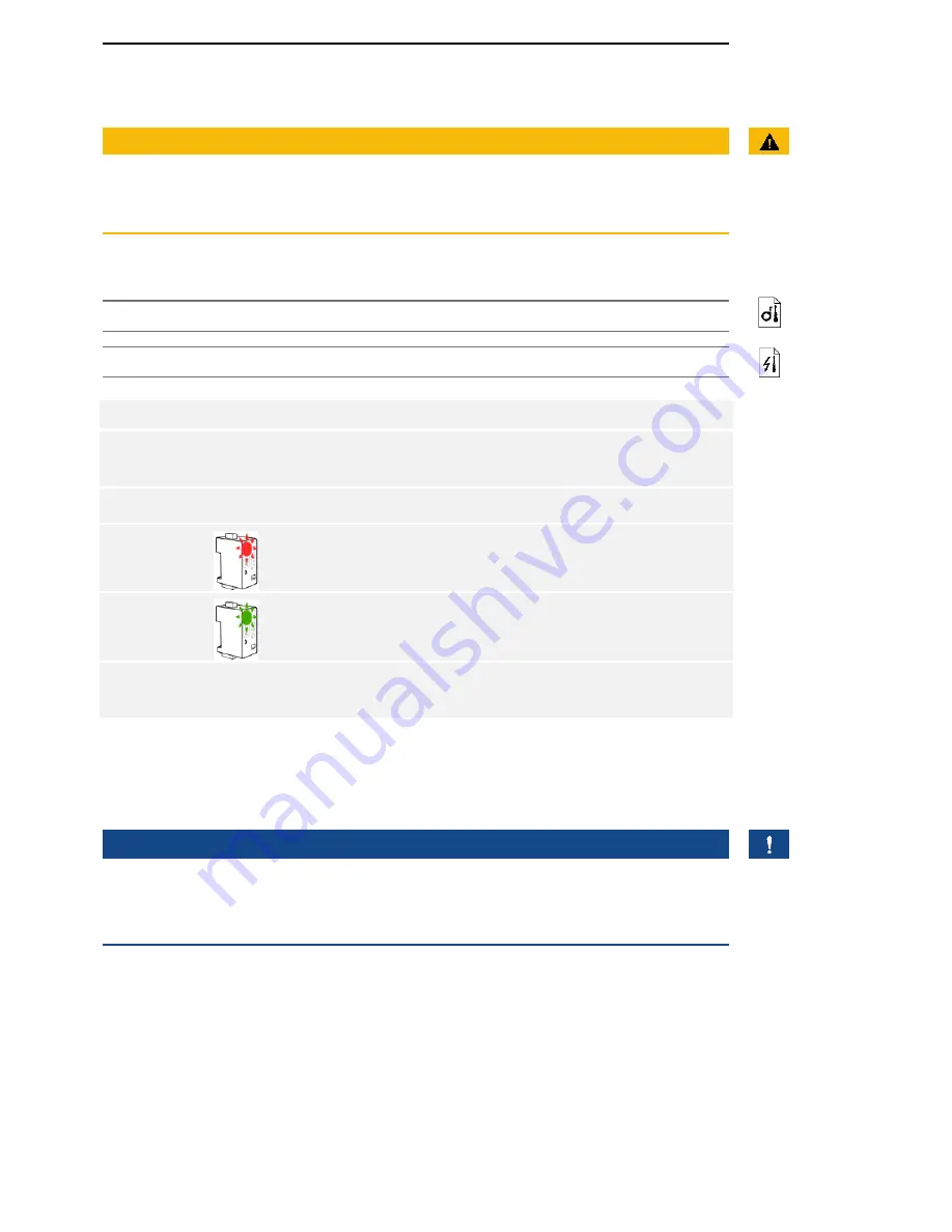
The status LED flashes red: incorrect connection. 

4.


The status LED flashes green: Normal mode. 

5.


If the LEDs fail to light up, check the wiring and 
power supply. 


The system has been installed and implemented. The data connection 
between the two systems has been established. The system is ready for 
use. 


NOTICE 

For information regarding the further processing of the sent 

 Wiegand 

ekey

data in the third-party Wiegand system, refer to the documents provided 
by the supplier of your Wiegand system. 


Summary of Contents for CV WIEG

Page 1: ...ekey home OPERATING INSTRUCTIONS en 01...

Page 2: ...g 3 Product description 4 System overview 4 Scope of delivery 4 Proper use and area of application 4 Wiegand converter 5 Configuration tool 6 Technical specifications 7 System setup variants 7 variant...

Page 3: ...t on the system devices by the operator These operating instructions are not subject to updating Subject to optical and technical modifications any liability for errors and misprints excluded Our gene...

Page 4: ...urer WIEG Wiegand Safety information DANGER All devices are to be operated with safety extra low ekey home voltage SELV Only use power supplies rated protection class 2 according to VDE 0140 1 Failure...

Page 5: ...y for a finger scan access control system The device is integrated into the system The system is comprised of a finger scanner control panel converter and third party Wiegand system It is available in...

Page 6: ...ignals on the converter 1 Status LED 2 Button Fig 2 Overview of ekey home CV WIEG RS485 The converter has a status LED for displaying operating statuses There is a button for resetting the device to i...

Page 7: ...r number and the finger number In an system this is calculated as follows ekey home User ID 10 finger number e g User number 15 with finger number 7 15 10 7 157 In an system the user ID is calculated...

Page 8: ...le 4 Technical specifications ekey home CV WIEG RS485 System setup variants There are three setup variants for connecting an or ekey home ekey multi system to a third party Wiegand system Fig 3 Overvi...

Page 9: ...The third party system must therefore be able to recognise various facility codes Fig 5 Overview of variant 2 ekey multi 1 Finger scanner 1 4 2 Wiegand converter 1 4 3 Third party Wiegand system 4 ek...

Page 10: ...he system Only one converter is used in the system and a distinction between the individual finger scanners does not need to be made in the third party Wiegand system variant 1 ekey multi The followin...

Page 11: ...ring diagram Fig 6 ATTENTION The device connections are not polarity reversal protected Possible property damage Check the configuration of the wires carefully before connecting the power supply Step...

Page 12: ...Instruction 1 Launch the software ekey FWupdate 2 The program automatically opens with the ekey FWupdate update window NOTICE This function enables you to download the most recent firmware software f...

Page 13: ...m the ekey converter USB dropdown menu based on the serial number 6 Click on Search 7 The connected is ekey home converter Wiegand RS485 listed The Wiegand button is enabled 8 Click on Wiegand 9 The i...

Page 14: ...tings Click on Cancel to discard the settings Configuration of the converter is complete The converter is ready for installation and implementation Below you will find configuration examples for the d...

Page 15: ...y multi variant 2 ekey multi In this example the serial numbers of the 4 finger scanners being assigned and the facility codes in the 4 converters being used have been entered in input line FS1 This c...

Page 16: ...ion of the devices Close the covers 2 Connect the power supply to the mains 3 The status LED flashes red incorrect connection 4 The status LED flashes green Normal mode 5 If the LEDs fail to light up...

Page 17: ...electronic equipment is to be recycled and may not be disposed of with household waste As disposal regulations within the EU can differ from country to country please contact your dealer for further i...

Page 18: ...Est Landstrasse 79 FL 9490 Vaduz Tel 41 71 560 54 80 of ce ekey ch Italy ekey biometric systems Srl Via del Vigneto 35 A I 39100 Bolzano Tel 39 0471 922 712 italia ekey net Germany ekey biometric syst...

Reviews: