background image

4. Troubleshooting

Problems

Possible cause and remedy

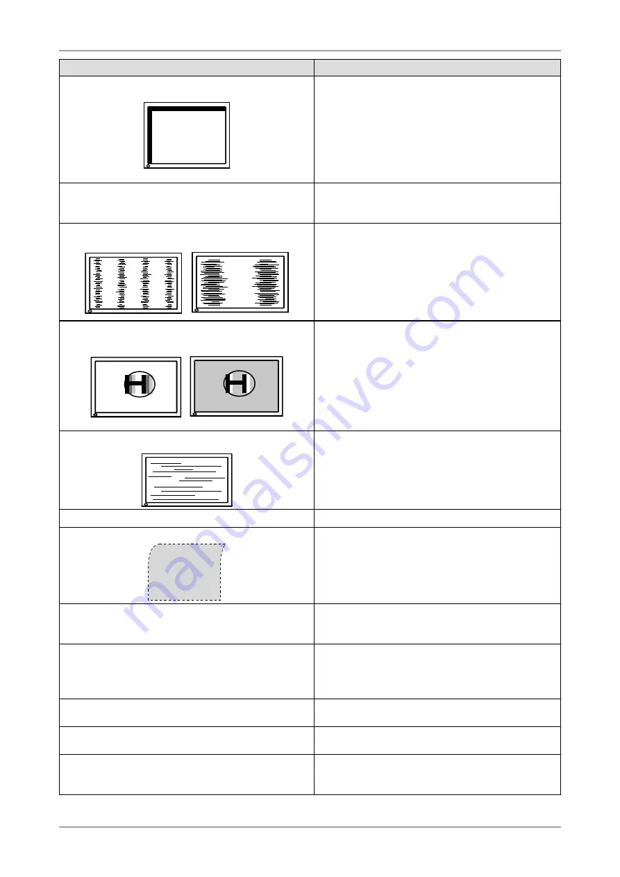
3. Display position is incorrect.

 Adjust image position so that it is displayed properly 

within the display area using the <Position> adjustment 
(page 15).

 Adjust image position so that it is displayed properly 

within the display area using the "Hor.Position" and "Ver.
Position" adjustment (page 15).

 If the problem persists, use the graphics board’s utility if 

available to change the display position.

4. Screen image displayed is smaller or larger than the 

actual screen image.

 Adjust the resolution using <Resolution> so that the 

input signal resolution equals the resolution in the 
resolution adjustment menu (page 16).

5. Vertical bars appear on the screen or a part of the image 

is flickering.

 Adjust using <Clock> (page 15).

6. The characters and images have several vertical bars on 

their right side.

 Adjust the characters and images using the  

<Signal Filter>.

7. Whole screen is flickering or blurring.

 Adjust using <Phase> (page 15).

8. Characters are blurred.

 Adjust using <Smoothing> (page 23).

9. Upper part of the screen is distorted as shown below. 

 This is caused when both composite sync (X-OR) 

signal and separate vertical sync signal are input 
simultaneously. Select either composite signal or 
separate signal

10.The screen is too bright or too dark.

 Adjust <Brightness>. (The LCD monitor backlight has a 

fixed life span. When the screen becomes dark or begins 
to flicker, contact your local dealer.)

11.Afterimages appear.

 Use a screen saver or off timer function for a long-time 

image display.

 Afterimages are particular to LCD monitors. Avoid 

displaying the same image for a long time.

12.Green/red/blue/white dots or defective dots remain on 

the screen.

 This is due to LCD panel characteristics and is not a 

failure.

13.Interference patterns or fingerprints remain on the 

screen.

 Leave the monitor with a white screen or a black screen. 

The symptom may disappear.

14.Noise appears on the screen.

 When entering the signals of analog input, select 1 to 

4 in <Signal Filter> from the <Screen> menu to change 
the mode.

Summary of Contents for FlexScan MX210

Page 1: ...ion 10 2 1 Connecting Two PCs to the Monitor 10 2 2 Making Use of USB Universal Serial Bus 11 3 Screen Adjustment and Settings 12 3 1 Basic Operation and Functions 12 3 2 Screen Adjustment 14 3 3 Colo...

Page 2: ...arrangements are made pursuant to EIZO NANAO CORPORATION s receipt of said information Although every effort has been made to ensure that this manual provides up to date information please note that E...

Page 3: ...ower connections immediately and contact your dealer for advice Attempting to use a malfunctioning unit may result in fire electric shock or equipment damage Do not open the cabinet or modify the unit...

Page 4: ...outlet of your country Be sure to remain within the rated voltage of the power cord Not doing so may result in fire or electric shock Power supply 100 120 200 240 Vac 50 60 Hz To disconnect the power...

Page 5: ...ing the unit with the cord attached is dangerous It may result in injury When handling the unit grip the bottom of the unit firmly with both hands ensuring the panel faces outward before lifting Dropp...

Page 6: ...l Leave the screen white or black to decrease the prints When the screen image is changed after displaying the same image for extended periods of time an afterimage may appear Use the screen saver or...

Page 7: ...mode supported 59 61Hz BrightRegulator function incorporate DICOM mode CAL Switch function CAL Switch function for selecting an optimal calibration mode Smoothing function incorporated for the adjust...

Page 8: ...gnal Selection button 4 Mode button 5 Auto Adjustment button 6 Enter button 7 Control buttons Left Down Up Right 8 Power button 9 Power indicator Indicator status Operation status Blue The screen is d...

Page 9: ...nt patterns and procedures on the screen RadiCS LE for Windogs RadiCS LE is quality control software used to calibrate the monitor and manage the calibration history A PC must be connected to the moni...

Page 10: ...or two seconds To set auto switching of input signals Input Signal The monitor recognizes the connector through which PC signals are input When either PC is turned off or enters the power saving mode...

Page 11: ...ls is recommended If the monitor is in the power saving mode or if the monitor is connected to the power outlet with the monitor turned off all the devices connected to the USB ports upstream and down...

Page 12: ...ustments and Settings 1 Select the desired sub menu icon using and press The sub menu appears 2 Use to select the desired setting icon and press The setting menu appears 3 Use to make all required adj...

Page 13: ...Menu Size Change the size of the menu Menu Position Adjust the menu position Menu Off Timer Set the menu displaying time Translucent Set the transparency of the background Orientation Set the orientat...

Page 14: ...in to automatically adjust the clock phase screen position and resolution If you do not wish to do adjust the screen do not press again NOTE The Auto adjustment function is intended for use on the Mac...

Page 15: ...ng or bars appear on the screen Use the Phase adjustment Select the Phase and eliminate the horizontal flickering blurring or bars by using and NOTE Horizontal bars may not completely disappear from t...

Page 16: ...lution using and 4 Adjust the output signal range Dynamic Range of the signal Use the Range Adjustment of Screen menu This controls the level of output signal range to display the whole color gradatio...

Page 17: ...AL Switch modes are as follows Mode Purpose DICOM CL Available for setting tailored to X ray film color clear base Text Suitable for displaying texts for word processing or spreadsheets Custom Availab...

Page 18: ...ed CAL Switch mode Settable Adjustable Fixed at the factory Icons Functions CAL Switch Mode DICOM CL Text Custom CAL Brightness Temperature Gamma Saturation Hue Gain 6 colors Reset These settings can...

Page 19: ...in the digital signal input is recommended If using the monitor in the analog input signal set the gamma value from 1 8 to 2 2 Saturation To change the saturation 100 100 Setting the minimum level 100...

Page 20: ...Input This monitor complies with the VESA DPMS standard and adopts a power saving method Procedure 1 Set the PC s power saving settings 2 Select VESA DPMS from the PowerManager menu Power Saving Syste...

Page 21: ...tional 90 minutes Extension of operation time can be set without limitation Power Resumption Procedure Press to return a normal screen NOTE The off timer function works while the PowerManager is activ...

Page 22: ...ator in the ScreenManager Others menu 2 Select Disable 3 8 Automatic brightness adjustment The sensor on the front side of the monitor detects the environmental brightness to adjust the screen brightn...

Page 23: ...irrespective of the picture s resolution Since the vertical resolution and horizontal resolution are enlarged at same rates some horizontal or vertical image maydisappear Normal Displays the picture a...

Page 24: ...t Menu Settings in the ScreenManager Others menu 2 Select Orientation in the Menu Settings menu 3 Use to select between Portrait and Landscape 3 11 EIZO Logo Appearing Function When switching on the p...

Page 25: ...ge Switch the input signal with Operate the mouse or keyboard Turn on the PC 2 The message below appears This message appears when the signal is not input correctly even when the monitor functions pro...

Page 26: ...s flickering or blurring Adjust using Phase page 15 8 Characters are blurred Adjust using Smoothing page 23 9 Upper part of the screen is distorted as shown below This is caused when both composite sy...

Page 27: ...tal signal is input Check for Adjustment Lock function page 21 19 PC is hung up The peripherals connected to the downstream ports do not operate Check that the USB cable is correctly connected Check t...

Page 28: ...he monitor without stand and attaching equipment such as a cable T V GS approved arm or stand Please connect cables after attaching an arm stand Setup Procedure 1 Hold the upper and lower centers of t...

Page 29: ...e to the cabinet or LCD panel Cabinet To remove stains wipe the cabinet with a soft lightly moistened cloth using a mild detergent Do not spray wax or cleaner directly into the cabinet For details ref...

Page 30: ...l Connector DVI I connector D Sub mini 15 pin Analog Input Signal Sync Separate TTL Positive Negative Composite TTL Positive Negative Analog Input Signal Video 0 7 Vp p 75 ohms Positive Input Signal D...

Page 31: ...g 3 CAL Switch Mode DICOM CL PowerManager Analog input VESA DPMS Digital input DVI DMPM Screen Size Full Off Timer Disable Menu Settings Menu Size Normal Menu Off Timer 45 seconds BrightRegulator Disa...

Page 32: ...ata0 C3 Analog Blue 8 Analog Vertical Sync 18 TMDS Data0 C4 Analog Horizontal Sync 9 TMDSData1 19 TMDS Data0 5 Shield C5 Analog Ground analog R G B return 10 TMDS Data1 20 NC NC No Connection D sub mi...

Page 33: ...anagement The Power management system for the digital interface The Monitor ON status operation mode and the Active Off status power saving mode are indispensable for the DVI DMPM as the monitor s pow...

Page 34: ...wer temperatures it appears somewhat red Computer monitors generally give best performance at high temperature settings 5000 K Slightly reddish white 6500 K Warm white tone similar to white paper or d...

Page 35: ...ive Vertical 74 76 Positive PC 9801 640 400 56Hz 21 0 MHz Horizontal 24 83 Negative Vertical 56 42 Negative PC 9821 640 400 70Hz 25 2 MHz Horizontal 31 48 Negative Vertical 70 10 Negative VESA 640 480...

Page 36: ...nergy saving mode after a certain time beneficial both for the user and environment Electrical safety Emissions Electromagnetic fields Noise emissions Ecology The products must be prepared for recycli...

Page 37: ...ference to radio communications However there is no guarantee that interference will not occur in a particular installation If this equipment does cause harmful interference to radio or television rec...

Page 38: ...n da die H he der Bildschirmmitte ber dem Boden zwischen 135 150 cm betr gt d Der Standfu mu die M glichkeit zur Neigung des Bildschirmger tes besitzen max vorw rts 5 min nach hinten 5 e Der Standfu m...

Page 39: ......

Reviews: