background image

English 


2. 

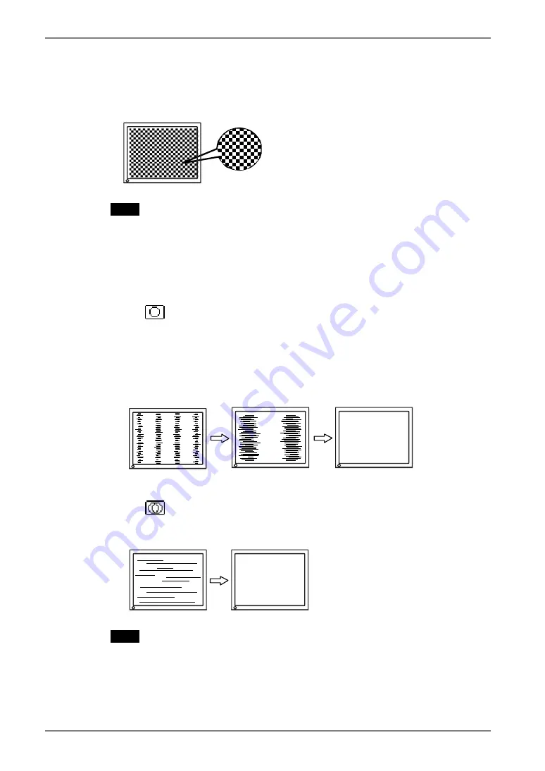
We recommend setting the desktop pattern to that as shown in the 
diagram below. 


NOTE


• 

More precise adjustment is available for using the “Screen Adjustment 
program” software.  It can be downloaded from the EIZO homepage 
(http://www.eizo.com). 

3. 

Adjust by using <Screen> menu in the ScreenManager. 

(1)  Vertical bars appear on the screen 


  Use the <Clock> (p.34) adjustment. 

Select the <Clock> and eliminate the vertical bars by using the Right and Left 
of the Control Buttons.  
Do not continuously press the Control Buttons, as the adjustment value will 
change quickly and make it difficult to locate the most suitable adjustment 
point.  If the horizontal flickering, blur or bars appear, proceed to <Phase> 
adjustment as follows. 


(2)  Horizontal bars appear on the screen.   


  Use the <Phase> (p.34) adjustment. 

Select the <Phase> and eliminate the horizontal flickering, blurring or bars by 
using the Right and Left Buttons. 


NOTE


• 

Horizontal bars may not completely disappear from the screen depending on 
the PC. 

22

 4. 

ADJUSTMENT 

Summary of Contents for FlexScan L560T-CB

Page 1: ......

Page 2: ...ference to radio communications However there is no guarantee that interference will not occur in a particular installation If this equipment does cause harmful interference to radio or television rec...

Page 3: ...User s Manual Touch Panel Color LCD Monitor It shall be assured that the final system is in compliance to IEC60601 1 1 requirements...

Page 4: ...reproduced stored in a retrieval system or transmitted in any form or by any means electronic mechanical or otherwise without the prior written permission of EIZO NANAO CORPORATION EIZO NANAO CORPORAT...

Page 5: ...g the signal cable 14 2 3 Touch Operation 16 2 4 Connecting two PCs to the monitor 16 3 ScreenManager 17 3 1 How to use the ScreenManager 17 3 2 Adjustments and Settings 18 3 3 Useful Functions 19 4 A...

Page 6: ...in the specifications To ensure personal safety and proper maintenance please read carefully this section and the caution statements on the monitor Location of the Caution Statements Symbols on the un...

Page 7: ...or liquid falls spills into the cabinet unplug the unit immediately Have the unit checked by a qualified service engineer before using it again SIG AUTO ENT Place the unit at the strong and stable pl...

Page 8: ...ectric shock or equipment damage Power Supply 100 120 200 240 Vac 50 60Hz Do not overload your power circuit as this may result in fire or electric shock Handle the power cord with care Do not place t...

Page 9: ...uipment damage OK Do not block the ventilation slots on the cabinet Do not place any objects on the ventilation slots Do not install the unit in a closed space Do not use the unit laid down or upside...

Page 10: ...he screen saver or timer to avoid displaying the same image for extended periods of time Periodic cleaning is recommended to keep the monitor looking new and to prolong its operation lifetime Refer to...

Page 11: ...tton cloth or lens cleaning paper Remove persistent stains gently with a cloth dampened with a little water and then clean the panel again with a dry cloth for better finishing NOTE Optional ScreenCle...

Page 12: ...provided USB serial communication Touch Panel Pointer TP1 is available optional p 16 1 2 Package Contents Please contact your local dealer for assistance if any of the listed items are missing or dam...

Page 13: ...g input only 4 ENT Enter Button Show the ScreenManager on the screen Confirm the setting adjustment function Save the adjustment values 5 Control Buttons Left Down Up Right Select the desired function...

Page 14: ...for connection of a security cable This lock supports Kensington s MicroSaver security system 11 Power Connector POWER INPUT Connect the power cord 12 DVI D Connector DVI Connect the optional digital...

Page 15: ...r computer and display support VESA DDC the suitable resolution and the refresh rate are set by just plugging your display into the computer without any manual settings Analog Input Resolution Frequen...

Page 16: ...ecting secure the connection with the screw in fasteners Analog Input Signal Cable Connector of PC Signal Cable enclosed MD C87 Video Output Connector D Sub mini 15 pin Input Connector monitor D Sub m...

Page 17: ...ESHOOTING p 27 for advice 4 Install the touch panel driver TouchWare for Windows 2000 XP or MT 7 for Windows Vista depending on your OS NOTE Regarding installing touch panel drivers and cautions pleas...

Page 18: ...monitor Two PCs can be connected to the monitor through the DVI and the D Sub mini 15 pin connector on the back of the monitor NOTE The touch panel operation is effective for one computer only Select...

Page 19: ...Button The setting menu appears 3 Use the Control Buttons to make all required adjustments and press the Enter Button to save the settings 3 Exiting the ScreenManager 1 To return to the main menu sel...

Page 20: ...ection of automatic or manual p 20 Off Timer Set the power save p 19 VGA Selection Select the display mode p 28 Menu Position Adjust the menu position Translucent Set the transparency of the menu Menu...

Page 21: ...ned amount of time has lapsed This function was created to reduce afterimage characteristics that are particular to LCD monitors when the monitor screen is left on for a long period without use Proced...

Page 22: ...splay 1 Turn off the monitor s power by the Power button 2 Hold down the Enter button once again and turn the power back on Automatically selecting the input signal function The monitor will automatic...

Page 23: ...on the control panel The message Your setting will be lost if you press again now appears and remains on the screen for 5 seconds While the message is on the screen press the Auto Adjustment Button ag...

Page 24: ...e vertical bars by using the Right and Left of the Control Buttons Do not continuously press the Control Buttons as the adjustment value will change quickly and make it difficult to locate the most su...

Page 25: ...the Range Adjustment p 34 This controls the level of output signal range to display the whole color gradation 256 colors Procedure Press the Auto Adjustment Button on the control panel while displayi...

Page 26: ...reference tool To create an uniform white or black screen the percentages for each will probably not be the same Adjustment Contents Color Mode Menu Custom sRGB Function Descriptions Adjustable range...

Page 27: ...may cause undisplayable color tone To change each color red green and blue 0 100 By adjusting the red green and blue color tones for each mode custom colors can be defined Display a white or gray back...

Page 28: ...the screw holes 100 mm x 100 mm Thickness of plate 2 6 mm Strong enough to support weight of the monitor unit except the stand and attachments such as cables Attach an arm or stand to meet the follow...

Page 29: ...e appear when the signal is not inputted correctly even if the monitor functions properly When the image is displayed correctly after a short time there is no problem with the monitor Some PCs do not...

Page 30: ...ars using the Clock p 22 5 Horizontal bars of distortion appear Decrease the horizontal bars using the Phase p 22 6 Letters and lines appear blurred Switch the Smoothing mode p 23 7 The screen is too...

Page 31: ...p 19 12 The Auto Adjustment Button does not operate The adjustment lock is probably on To unlock switch the LCD monitor off Then while pressing the Auto Adjustment Button switch the power on p 19 The...

Page 32: ...ve seconds later after appearing the image Touch the screen five seconds later after connecting the USB cable Changing the position or angle of the monitor will cause cursor jump The drawing touch and...

Page 33: ...ll speed Touch Panel Detective method Analog capacitive technology finger touch Power Supply 100 120 200 240 VAC 10 50 60 Hz 0 55 0 5 A 0 35 0 3 A Power Consumption Max 32 W Input Connector D Sub mini...

Page 34: ...approx 6500 K Input Signal Auto Off Timer Disable Language English Optional Touch Panel Pointer TP1 Signal Cable FD C39 Cleaning kit EIZO ScreenCleaner Dimensions Unit mm inches 5 761 06 325 5 12 8 16...

Page 35: ...2 9 TMDS Data1 17 TMDS Data0 2 TMDS Data2 10 TMDS Data1 18 TMDS Data0 3 TMDS Data2 4 Shield 11 TMDS Data1 3 Shield 19 TMDS Data0 5 Shield 4 NC 12 NC 20 NC 5 NC 13 NC 21 NC 6 DDC Clock SCL 14 5V Power...

Page 36: ...ion method TMDS There are two kinds of DVI connectors One is DVI D connector for digital signal input only The other is DVI I connector for both digital and analog signal inputs Gain Adjusts each colo...

Page 37: ...displayed as a full screen 1 1 sRGB Standard RGB International Standard for Red Green and Blue color space A color space was defined with the aim of the color matching between applications and hardwa...

Page 38: ...t Clock MHz H V H kHz V Hz VGA Graphics 320 x 200 25 2 Nega Nega 31 47 70 09 VGA 640 x 480 25 2 Nega Nega 31 47 59 94 VGA TEXT 720 x 400 28 3 Nega Posi 31 47 70 09 VESA 640 x 480 31 5 Nega Nega 37 86...

Page 39: ...peration in the configuration in which it will be used Guidance and manufacturer s declaration electromagnetic emissions The FlexScan L560T CB is intended for use in the electromagnetic environment sp...

Page 40: ...line s to earth 1kV line s to line s 2kV line s to earth Mains power quality should be that of a typical commercial or hospital environment Voltage dips short interruptions and voltage variations on...

Page 41: ...as determined by an electromagnetic site surveya should be less than the compliance level in each frequency rangeb Interference may occur in the vicinity of equipment marked with the following symbol...

Page 42: ...150kHz to 80MHz d 1 2 P 80MHz to 800MHz d 1 2 P 800MHz to 2 5GHz d 2 3 P 0 01 0 12 0 12 0 23 0 1 0 38 0 38 0 73 1 1 2 1 2 2 3 10 3 8 3 8 7 3 100 12 12 23 For transmitters rated at a maximum output po...

Page 43: ......

Reviews: