background image

21

Chapter 3 If No Image Is Displayed

Chapter 3  If No Image Is Displayed

Problem

Possible cause and remedy

1.  No picture

 • Power indicator does not light up.

 • Check whether the power cord is connected properly.
 • Check whether the DC OUT terminal and the DC IN terminal 

are connected properly.

 • Turn on the power switch.
 • Check whether the main power indicator of the AC adapter is 

on.

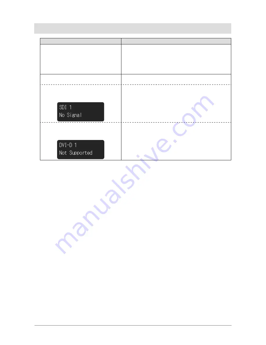
2.  The message below appears.

This message appears when the signal is not input correctly even 
though the monitor is functioning properly.

 • This message appears when no signal is 

input.  
Example:

 • The message shown at left may appear, because some 

devices to be connected do not output the signal immediately 
after power-on.

 • Check whether the device to be connected is turned on.
 • Check whether the signal cable is connected properly.
 • Turn off the power, and then turn it on again.

 • The message indicates that the input signal 

is outside the specified frequency range. 


Example:


 •

Check whether the device to be connected is configured to 

meet the resolution and vertical scan frequency requirements 
of the monitor.

 • Reboot the device to be connected.

Summary of Contents for CuratOR EX2620

Page 1: ...ation Manual separate volume carefully to familiarize yourself with safe and effective usage Please retain this manual for future reference For monitor adjustment and settings refer to the Installation Manual The latest Instructions for Use is available for download from our web site http www eizoglobal com ...

Page 2: ...e unit This product has been adjusted specifically for use in the region to which it was originally shipped If operated outside this region the product may not perform as stated in the specifications No part of this manual may be reproduced stored in a retrieval system or transmitted in any form or by any means electronic mechanical or otherwise without the prior written permission of EIZO Corpora...

Page 3: ...WARNUNG Symbols on the unit Symbol This symbol indicates Power Switch Press to turn the monitor s power off Power Switch Press to turn the monitor s power on Direct current Alerting electrical hazard CAUTION Refer to SAFETY SYMBOLS page 2 Potential equalization terminal WEEE marking Product must be disposed of separately materials may be recycled CE marking EU conformity mark in accordance with th...

Page 4: ...correctly on a sufficiently strong desk or wall If the unit is installed incorrectly it may drop or fall over and result in personal injury or equipment damage If the unit falls disconnect the power immediately and ask your local EIZO representative for advice Do not continue using a damaged unit Using a damaged unit may result in fire or electric shock Use the unit in an appropriate location Othe...

Page 5: ...his Instructions for Use may cause fire electric shock or equipment damage Power supply 100 240Vac 50 60Hz Do not overload your power circuit as this may result in fire or electric shock Handle the power cord and AC adapter with care Handle the power cord and AC adapter with care Do not place heavy objects on pull or tie the power cord or the AC adapter Using a damaged cord or AC adapter may resul...

Page 6: ...nadequate space Do not use the unit laid down or upside down Blocking the ventilation slots prevents proper airflow and may result in fire electric shock or equipment damage Do not touch the plug or AC adapter with wet hands Doing so may result in electrical shock Use an easily accessible power outlet This is to facilitate disconnecting the power in case of a problem Mind that the AC adapter becom...

Page 7: ...n the plug may result in fire Unplug the unit before cleaning it Cleaning the unit while it is plugged into a power outlet may result in electric shock If you plan to leave the unit unused for an extended period of time disconnect the power cord from the wall socket after turning off the power switch for the safety and the power conservation English ...

Page 8: ... off for a few hours may solve the problem The backlight of the LCD panel has a fixed lifetime When the screen becomes dark or begins to flicker please contact your local EIZO representative The screen may have defective pixels or a small number of light dots on the screen This is due to the characteristics of the panel itself and is not a malfunction of the product Do not press on the panel or ed...

Page 9: ...roxide solution Alkyldiaminoethylglycine hydrochloride Satenidin solution Benzalkonium chloride Zalkonin solution Benzethonium chloride Bezeton solution Attention Do not use chemicals on a frequent basis Chemicals such as alcohol and antiseptic solution may cause gloss variation tarnishing and fading of the cabinet or panel and also quality deterioration of the image Never use any thinner benzene ...

Page 10: ...6 2 1 Before Installing the Product 16 Installation Requirements 16 2 2 Installing the Product 17 2 3 Connecting the Power Cord 18 2 4 Connecting the Cables 19 2 5 Installing the Cable Cover 20 2 6 Turning On the Power 20 Chapter 3 If No Image Is Displayed 21 Chapter 4 Specifications 22 4 1 Specifications List 22 4 2 Displayable Input Signals 2D 24 4 3 Displayable Input Signals 3D 25 4 4 Optional ...

Page 11: ... 3G SDI signal 2 inputs 2 outputs Also supports dual stream system DVI signal 2 inputs 1 output Simultaneous input of two types of HD images is possible Component Analog RGB signal 1 input 1 output S VIDEO signal 1 input 1 output Composite video signal 1 input 1 output Analog RGB signal 1 input Other functions 2 screen display function Parallel display of two input images is possible Two modes P i...

Page 12: ... adapter AHM100PS24 Cable cover with screws Monitor attachment screw M4 12 x 4 3D fogless polarized glasses x 3 User s Manual CD Instructions for Use 1 3 Controls and Functions AC adapter 2 3 1 1 Main power indicator Depending on the operation status of the main power supply the indicator of the AC adapter turns on or off Lit up Power on Not lit up Power off 2 AC IN terminal Connects the power cor...

Page 13: ...Executes the function assigned to this button Select items in the menu screen 5 F2 button 6 F3 button 7 F4 button 8 3D 2D ENTER button Switches the 3D and 2D displays Select items in the menu screen 9 Power indicator The indicator color differs depending on the monitor s operation status Green Monitor in operation Orange Power saving mode Off Power off 10 Power switch Turns the power on or off On ...

Page 14: ...s having R for RGB output 16 SYNC input terminal BNC type When this product is operated externally synchronized connects devices having C SYNC standard signal output 17 GPI input terminal D Sub 9pin Connects to GPI supported external devices By assigning functions to each terminal this product can be controlled by external devices 18 RS 232C terminal D Sub 9pin Controls this product by connecting ...

Page 15: ...input terminal BNC type Connects devices having SDI output terminals 29 SDI 1 2 output terminal BNC type The signal input to SDI 1 2 input terminal is output as is 30 DVI D 1 2 input terminal DVI D Connects devices having DVI D output 31 DVI D 2 output terminal DVI D The signal input to DVI D 2 input terminal is output as is 32 Potential equalization terminal This is a terminal for ensuring equal ...

Page 16: ...orough operational testing of the system cables arms etc in the environment where the product will be used Installation Requirements When installing the monitor ensure that there is adequate space around the sides back top and bottom of the monitor Attention Position the monitor so that there is no light to interfere with the screen Do not use any materials or objects that will cover the monitor o...

Page 17: ...r Up 45 down 45 Connect the cables after attaching an arm or stand The monitor arm and stand are heavy Dropping them may result in injury or equipment damage Periodically check the tightness of the screws If not sufficiently tight the monitor may detach from the arm which may result in injury or equipment damage 1 Attach the arm or stand to the back of the monitor by aligning the four screw holes ...

Page 18: ...er to the DC IN terminal on the monitor Align the connector shape with the port shape rotate the lock ring clockwise and fix it securely Note If the lock ring does not rotate easily push it in further and retry it Lock ring 3 Check the rated value on the AC adapter and connect the power plug to the power outlet Attention Do not install the AC adapter in a vertical position with the power plug inse...

Page 19: ...nal and DVI D terminal are vulnerable to static electricity so be sure to work with care at installation When working with the monitor be sure to observe the following Do not touch the connector pins Do not touch pins at the end of any cable connected to a connector Take anti static precautions such as using an anti static wrist strap when working Note The warning label is displayed as shown in th...

Page 20: ...Ensure that cables are not pinched between the cable cover and the monitor Securely tighten the screws in the two locations Screw tightening torque 0 4 N m to 0 7 N m Avoid subjecting the terminal and cable to stress Do not pack or transport if the cable cover is attached 2 6 Turning On the Power 1 Turn on the power switch at the bottom of the monitor and then turn on the monitor The power indicat...

Page 21: ...t correctly even though the monitor is functioning properly This message appears when no signal is input Example The message shown at left may appear because some devices to be connected do not output the signal immediately after power on Check whether the device to be connected is turned on Check whether the signal cable is connected properly Turn off the power and then turn it on again The messa...

Page 22: ...uding synchronous signals PB B 0 7 Vp p 75 Ω PR R 0 7 Vp p 75 Ω Sync 0 3 Vp p to 4 0Vp p 75 Ω Composite video BNC 1 1 0 Vp p 75 Ω S VIDEO 4pin mini DIN x 1 Brightness signal 1 0 Vp p 75 Ω Color signal 0 286 Vp p 75 Ω Output Terminal DVI DVI D 1 Single link DVI D HDCP unsupported SDI BNC 2 3G HD SD SDI Component Analog RGB BNC 4 1 Y G 1 0 Vp p 75 Ω including synchronous signals PB B 0 7 Vp p 75 Ω P...

Page 23: ...sure 540 hPa to 1060 hPa AC adapter Power Input 100 240 VAC 10 50 60 Hz 1 2 A Maximum Power Consumption Max 95 W Physical Specifications Outside dimensions W H D 160 mm 37 mm 64 mm Net Weight Approx 0 7 kg Operating Environmental Requirements Temperature 0 C to 35 C 32 F to 95 F Humidity 20 to 85 R H no condensation Air Pressure 540 hPa 1060 hPa Transportation Storage Environmental Requirements Te...

Page 24: ... 069 1024 x 768 75Hz 60 023 75 029 1024 x 768 85Hz 68 677 84 997 1152 x 864 75Hz 67 500 75 000 1280 x 768 60Hz 47 776 59 870 3 3 1280 x 800 60Hz 49 702 59 810 1280 x 960 60Hz 60 000 60 000 1280 x 1024 60Hz 63 981 60 020 1280 x 1024 75Hz 79 976 75 025 1400 x 1050 60Hz 65 317 59 978 3 3 1440 x 900 60Hz 55 935 59 887 1680 x 1050 60Hz 65 290 59 954 3 3 1600 x 1200 60Hz 75 000 60 000 3 3 1920 x 1080 60...

Page 25: ...ported Signal name Horizontal Frequency kHz Vertical Frequency Hz SDI 1 SDI 2 DVI D 1 DVI D 2 720 60p 45 000 60 000 720 50p 37 500 50 000 1080 60i 33 750 60 000 1080 60p 67 500 60 000 1080 50i 28 125 50 000 1080 50p 56 250 50 000 1080 30p 33 750 30 000 1080 25p 28 125 25 000 1080 24p 27 000 24 000 1080 24PsF 27 000 48 000 1024 x 768 60Hz 48 363 60 004 1280 x 1024 60Hz 63 981 60 020 4 4 Optional Ac...

Page 26: ...c waves that could influence limit or result in malfunction of the monitor Install the equipment in a controlled environment where such effects are avoided Classification of Equipment Type of protection against electric shock Class I EMC class EN60601 1 2 2015 Group 1 Class B Classification of medical device MDD 93 42 EEC Class I Mode of operation Continuous IP Class IP32 ...

Page 27: ...or stacked use is necessary the equipment or system should be observed to verify normal operation in the configuration in which it will be used When using a portable RF communication equipment keep it 30 cm 12 inches or more away from any part including cables of the EX2620 3D Otherwise degradation of the performance of this equipment could result Anyone who connects additional equipment to the si...

Page 28: ...is charge ESD IEC EN61000 4 2 8 kV contact discharge 15 kV air discharge 8 kV contact discharge 15 kV air discharge Floors should be wood concrete or ceramic tile If floors are covered with synthetic material the relative humidity should be at least 30 Electrical fast tran sients bursts IEC EN61000 4 4 2 kV power lines 1 kV input output lines 2 kV power lines 1 kV input output lines Mains power qu...

Page 29: ...urveya should be less than the compliance level in each frequency rangeb Interference may occur in the vicinity of equip ment marked with the following symbol Note 1 UT is the a c mains voltage prior to application of the test level Note 2 At 80 MHz and 800 MHz the higher frequency range applies Note 3 Guidelines regarding conducted disturbances induced by RF fields or radiated RF fields may not a...

Page 30: ...3 28 28 5240 5100 5800 WLAN 802 11 a n Pulse modulation b 217 Hz 0 2 0 3 9 9 5500 5785 a For some services only the uplink frequencies are included b carrier are modulated using a 50 duty cycle square wave signal The EX2620 3D is intended for use in an electromagnetic environment in which radiated RF disturbances are controlled For other portable and mobile RF communication equipments transmitters...

Page 31: ...ill required to correct the interference at his own expense Changes or modifications not expressly approved by the party responsible for compliance could void the user s authority to operate the equipment Note Use the specified cable below so as to keep interference within the limits of a Class A digital device AC Cord Shielded Signal Cable Canadian Notice This Class A information technology equip...

Page 32: ...on All rights reserved http www eizoglobal com Siemensallee 84 76187 Karlsruhe Germany 中国苏州市苏州工业园区展业路 8 号中新科技工业坊 5B 153 Shimokashiwano Hakusan Ishikawa 924 8566 Japan 1st Edition June 2017 Printed in Japan 00N0N007A1 IFU EX26203D 6 ...

Reviews: