background image

56

Choose the running speed of cooling fans from the following options.


Normal

 ......  Operate in this mode under normal conditions.


Max

 ...........  Use this mode when you want to increase the cooling 

effect when operating the projector in high ambient 

temperature environment. Fan noise is louder than 

Normal

Setting

Simple mode buttons

Only these buttons are active 

when the simple mode is 

set to 

On

. [ON, STAND-BY, 

INPUT, AUTO PC, SHUTTER, 

MENU, SCREEN, POINTER, 

P-TIMER, ▲▼◄►, SELECT, 

VOL.+, VOL.-, L-CLICK, 

R-CLINK, MUTE, ON/OFF 

switch] Number buttons (p.14) 

also become active only when 

setting the remote control 

codes numbers or entering the 

PIN code numbers (pp. 54, 60).

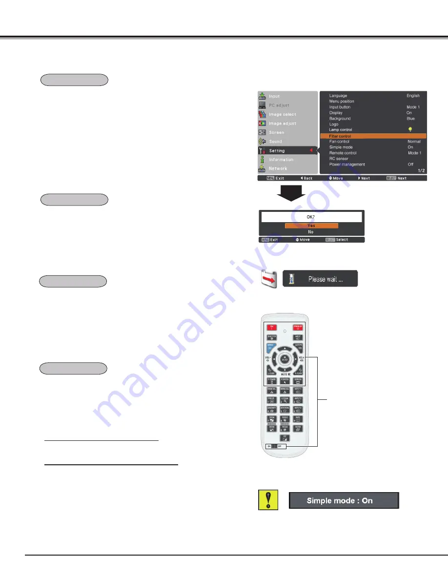
Filter control

This function decides whether to activate the simple mode.
 

Off

  . . . .  Simple mode function is off.


On

  . . . .  Only the simple mode buttons are active.

You can replace the filter with this function. Press the SELECT 

button at 

Filter control

 to display a confirmation box. To replace, 

press the SELECT button at 

yes

 and the electrically operated filter 

starts to scroll.

Note:

  •  Filter replacement icon and

 Please wait...


message appear on the screen 

when the filter is being scrolled.

  • The filter cannot be rewound.

  • When the filter is replaced, the total accumulated time of the filter use is 

    automatically set to 

0

.

A confirmation box appears and 

then select 

yes

.

Back

The eight different remote control codes (

Code 1

-

Code 8

) are 

assigned to the projector; the factory-set, initial code (

Code 1

) and 

the other seven codes (

Code 2

 to 

Code 8

). 

The same code should be set on both the projector and the remote 

control. For example, operating the projector in 

Code 7

, the remote 

control code also must be switched to 

Code 7

.


To change the code for the projector

  Select a remote control code in this Setting Menu.


To change the code for the remote control:

  Press and hold the MENU button and a number button (1-8) on   

  the remote control for more than five seconds to switch between 

  the codes. See “Remote Control Code” on page 16.

Note:

• When different codes are set on the projector and on the remote 
  control, any operation cannot be made. In that case, switch the code on 
  the remote control to fit the code on the projector.

Filter control

Fan control

Simple mode

Remote control


Note:


Warning icon and 

Simple mode : On

 message appear on the screen for 


about  4  seconds  when  press  the  button  which  is  not  the  simple  mode 

button.

Summary of Contents for LC-XL100A

Page 1: ...als below for details about network function Network Set up and Operation PJ Network Manager Multimedia Projector Owner s Manual LC XL100A LC XL200A LC XL100AL LC XL200AL MODEL Lens is optional for th...

Page 2: ...during a presentation pp 29 43 Security Function The Security function helps you to ensure security of the projector With the Key lock function you can lock the operation on the side control or remote...

Page 3: ...Control 29 Keystone Correction 31 Pointer Function 32 Wireless Mouse Operation 32 Input Selection 33 Direct Operation 33 Computer Input Source Selection 34 Video Input Source Selection 35 Computer Inp...

Page 4: ...MANUAL WITH THIS UNIT CAUTION RISK OF ELECTRIC SHOCK DO NOT OPEN Before installing and operating the projector read this manual thoroughly The projector provides many convenient features and functions...

Page 5: ...ut parts that could result in a fire or electric shock Never spill liquid of any kind on the projector Do not install the projector near the ventilation duct of air conditioning equipment This project...

Page 6: ...ted in the intake vents to prevent dust from getting inside of the projector In order to care for the projector appropriately regular cleaning is required Remove any dirt or dust that has accumulated...

Page 7: ...rees right and left In downward projection do not tilt the projector over 10 degrees right and left For ceiling mounting you need the ceiling mount kit designed for this projector When not mounted pro...

Page 8: ...se before it is cooled enough Do not hold the lens or the lens compartment tube when lifting or moving the projector Doing so may cause damage to the lens and the projector Care must be taken when han...

Page 9: ...this projector meets the requirement for use in the country you purchased it AC Power Cord for the United States and Canada AC Power Cord used in the United States and Canada is listed by the Underwr...

Page 10: ...t Power Cord Connector Rear Cover Optional Parts Attachment Hand Grip Security Chain Hook Note This is not a handle for carrying the projector Do not carry the projector with this hook Adjustable Feet...

Page 11: ...Y Pb Cb and Pr Cr jacks or connect the computer output signal 5 BNC Type Green Blue Red Horiz Sync and Vert Sync to G B R H V and V jacks pp 19 21 Part Names and Functions S VIDEO INPUT JACK Connect...

Page 12: ...m p 25 Expand or compress the image in the Digital zoom mode p 43 LAMP indicator Light red during operations LAMP REPLACE indicator Light orange when the projection lamp reaches its end of life pp 66...

Page 13: ...d with Point button p 28 To ensure safe operation observe the following precautions Do not bend drop or expose the remote control to moisture or heat For cleaning use a soft dry cloth Do not apply ben...

Page 14: ...LENS SHIFT button Select the Lens Shift function p 29 P TIMER button Operate the P timer function pp 30 58 Number buttons Act as number buttons Use these buttons when setting the remote control codes...

Page 15: ...guidelines Point the remote control toward the projector to Infrared Remote Receivers when pressing the buttons Maximum operating range for the remote control is about 16 4 5 m and 60 degrees in fron...

Page 16: ...h between the codes 1 To reset the remote control code press and hold the MENU and the number button 0 for more than five seconds 2 Press and hold the MENU and a number button 1 8 that corresponds to...

Page 17: ...position can be shifted upward up to 60 elevation of the display The display position can be shifted downward up to 60 low level of the display The display position can be shifted to the left in up t...

Page 18: ...ed the projector Lens Installation Shift the lens to the center position by using the Lens shift function p 27 1 2 Removing the lens Lens release button CAUTION Be careful when handling the lens Do no...

Page 19: ...g cables Cables used for connection Cables not supplied with this projector VGA Cable One cable is supplied DVI Digital cable BNC cable Serial Cross cable USB cable Monitor Output DIGITAL IN ANALOG IN...

Page 20: ...RGB YES Video YES Y Pb Cb Pr Cr YES Input 3 RCA Y Pb Cb Pr Cr YES S video S video NO Video Video YES Network NO Analog Out Signal Table A cable with one end D sub 15 and the other end Black box compa...

Page 21: ...e AC outlet before connecting cables Cables used for connection Cables not supplied with this projector Audio Output Installation Audio cable stereo R L External Audio Equipment Audio Input AUDIO OUT...

Page 22: ...untry where you use the projector Confirm the AC plug type with the chart below and proper AC power cord must be used If the supplied AC power cord does not match your AC outlet contact your sales dea...

Page 23: ...earched automatically p 51 If you press the ON STAND BY button on the side control or the remote control during the countdown period you can skip the countdown and go to the normal operations In this...

Page 24: ...ctor during this cooling down period 1 2 TO MAINTAIN THE LIFE OF THE LAMP ONCE YOU TURN THE PROJECTOR ON WAIT AT LEAST FIVE MINUTES BEFORE TURNING IT OFF DO NOT UNPLUG THE AC POWER CORD WHILE COOLING...

Page 25: ...ELECT button to set or access the selected item Press the MENU button on the side control or the remote control to display the On Screen Menu 1 2 3 Use the Point buttons to adjust the setting or switc...

Page 26: ...parameters to match with the input signal format pp 37 39 Screen For computer source used to adjust the size of the image Normal True Wide Full Custom Digital zoom Keystone Ceiling Rear Reset pp 42 4...

Page 27: ...and out the image Zoom Adjustment Display Focus on the screen Use the Point buttons to adjust focus of the image Focus Adjustment Side Control Lens Operation Zoom Zoom Focus Lens Shift Basic Operatio...

Page 28: ...again to turn the sound back on Use the Point buttons to select the desired submenu item and press the SELECT button to access the selected item Volume Volume Mute Press the Point button to turn up th...

Page 29: ...ting to the factory default setting SCREEN button Press the D ZOOM button on the remote control to enter to the Digital zoom mode See page 43 for details D ZOOM button Information display can be used...

Page 30: ...ove the pointer on the screen with this button MOUSE POINTER button POINTER button Press POINTER button on the remote control to display the Pointer on the screen Press the P TIMER button on the remot...

Page 31: ...in the Corner pattern function See Keystone on pages 44 50 The adjustable range is limited depending on the input signal Standard and Corner correction functions cannot be adjusted at the same time If...

Page 32: ...omputer and the projector with a USB cable p 19 When the Pointer function is used the wireless mouse is not available When a USB cable is connected to the computer and the projector turn on the projec...

Page 33: ...on the remote control The input source appears on the screen as you press each button Select the connected input source INPUT 1 button Input 1 RGB PC analog RGB Scart RGB PC digital RGB AV HDCP INPUT...

Page 34: ...BNC Type Green Blue Red Horiz Sync and Vert Sync from the computer to G B R H HV and V jacks Input Selection When your computer is connected to the INPUT 2 5 BNC INPUT JACKS terminal select RGB RGB 1...

Page 35: ...o the INPUT 1 ANALOG terminal select RGB Scart If the HDCP compatible signal source is connected to the INPUT 1 DIGITAL terminal select RGB AV HDCP Y Pb Cb Pr Cr INPUT 2 MENU Y Pb Cb Pr Cr INPUT 3 MEN...

Page 36: ...lly detects the signal format and tunes to project a proper image without any additional settings Signal formats provided in this projector are shown on pages 79 80 One of the following messages may a...

Page 37: ...nu Depending on the condition of signals and the type and length of cables the signals may not be properly viewed The Auto PC adjustment function can be operated directly by pressing the AUTO PC butto...

Page 38: ...to adjust the clamp level When the image has dark bars try this adjustment Use the Point buttons to adjust the horizontal area displayed by this projector Use the Point buttons to adjusts the vertical...

Page 39: ...1344 Position H 255 Position V 34 Display area H 1024 Display area V 768 Where to store Vacant This mode has stored parameters Values of Total dots Position H Position V Display area H and Display ar...

Page 40: ...Screen Menu Use the Point buttons to select Image select and then press the Point or the SELECT button Use the Point buttons to select the desired item and then press the SELECT button Standard Real I...

Page 41: ...int button to deepen green tone from 0 to 63 Press the Point button to lighten blue tone press the Point button to deepen blue tone from 0 to 63 Use the Point buttons to select the desired Color temp...

Page 42: ...selected when no signal is detected in the PC System Menu p 36 1 2 Press the MENU button to display the On Screen Menu Use the Point buttons to select Screen and then press the Point or the SELECT bu...

Page 43: ...and D zoom appears Press the SELECT button to expand the image size Use the Point buttons to pan the image The Panning function can work only when the image is larger than the screen size You can also...

Page 44: ...l be left right reversed This function is used to project the image from rear of the screen Keystone Ceiling Rear Reset Adjust the Horizontal Vertical keystone distortion of the projected image Standa...

Page 45: ...manually Video Input 1 AV System Menu Video or S video AV System Menu Y Pb Cb Pr Cr 2 Input 1 RGB PC analog Input 2 RGB Input 3 Video System NTSC Input 1 RGB PC analog Input 2 RGB Input 3 Y Pb Cb Pr...

Page 46: ...mage 8 Image 9 Image 10 Image select Menu 1 2 Press the MENU button to display the On Screen Menu Use the Point buttons to select Image select and then press the Point or the SELECT button Use the Poi...

Page 47: ...e Point buttons to adjust the tint value to get a proper color balance from 0 to 63 Note When White balance Red Green or Blue is adjusted the Color temp level will change to Adj Tint cannot be selecte...

Page 48: ...or 720p is selected p 45 Noise reduction cannot be selected when 1080p is selected p 45 To reset the adjusted data select Reset and press the SELECT button A confirmation box appears and then select Y...

Page 49: ...Press the Point button at Custom and the Custom is displayed on the screen you can use the Point buttons to choose the item you want to adjust Scale H V Adjust the Horizontal Vertical screen scale H...

Page 50: ...tortion of the projected image Use the Point buttons to choose the item you want to adjust Keystone Adjust the Horizontal Vertical keystone distortion of the projected image Standard Corner correction...

Page 51: ...he On Screen Menu Select Menu position and press the SELECT button The Menu position changes each time you press the SELECT button as follows the top left the top right the center the bottom left the...

Page 52: ...ce Setting Select the background screen for when no input signal is detected Press the Point buttons to switch between each option Blue Project a blue background Black Project a black background It is...

Page 53: ...When capturing the image that has been adjusted by the Keystone function the adjusted data is automatically reset and the projector captures an image without keystone correction When Logo PIN code loc...

Page 54: ...four digit number Press the Point button to select Logo PIN code change and then press the SELECT button The New Logo PIN code input dialog box appears Set a new Logo PIN code Be sure to note the new...

Page 55: ...de will be active after the lamp is sta bilized If Mode 2 has been selected and the projection lamp exceeds the recommended total hours of use the replacement icon will be displayed at the time of pow...

Page 56: ...the screen when the filter is being scrolled The filter cannot be rewound When the filter is replaced the total accumulated time of the filter use is automatically set to 0 A confirmation box appears...

Page 57: ...green blinking In this condition the projection lamp will be turned on if the input signal is reconnected or any button on the side control or remote control is pressed Shut down When the lamp has be...

Page 58: ...the following options Count up The P timer display 000 00 appears on the screen and the count starts 000 00 180 00 Count down The time set in the Timer setting appears on the screen and the countdown...

Page 59: ...PIN code lock function to set the security for the projector operation This function prevents the projector from being operated by unauthorized persons and provides the following setting options for...

Page 60: ...utton so that you can start to operate the projector If you entered an incorrect PIN code PIN code and the number will turn red for a moment Enter the correct PIN code all over again Enter a PIN code...

Page 61: ...down time has elapsed the shutter will be opened up automatically and the lamp will be turned off to cool itself down The SHUTTER indicator is blinking blue during this cooling off period When the lam...

Page 62: ...CT button to access the submenu items Filter counter Show the total accumulated time of the filter use timer setting Timer To set a timer when the projector reaches the time the Filter replacement ico...

Page 63: ...ormal condition the filter cartridge is not installed properly or the filter scroll is not working properly p 78 Fig 1 Filter replacement icon Fig 4 Filter cartridge replacement icon Fig 3 Last scroll...

Page 64: ...r on the filter cartridge s tab and then pull Latch Filter cartridge Tab RECOMMENDATION We recommend avoiding dusty smoky environments when operating the projector Usage in these environments may caus...

Page 65: ...uttons to select Setting and then press the Point or the SELECT button Use the Point buttons to select Filter counter and then press the SELECT button Use the Point buttons to select Filter counter Re...

Page 66: ...aches its end of life the Lamp replacement icon appears on the screen and LAMP REPLACE indicator lights orange Replace the lamp with a new one promptly The timing when the LAMP REPLACE indicator shoul...

Page 67: ...he Lamp Replacement section of this manual Continuous use of the lamp with the LAMP REPLACE indicator lighted may increase the risk of lamp explosion Lamp may explode as a result of vibration shock or...

Page 68: ...d finish with a soft dry cleaning cloth Avoid using an excessive amount of cleaner Abrasive cleaners solvents or other harsh chemicals might scratch the surface of the cabinet When the projector is no...

Page 69: ...ilated Check the installing condition to see if the air vents of the projector are not blocked Has the projector been installed near an Air Conditioning Heating Duct or Vent Move the installation of t...

Page 70: ...Check the projection lamp See page 66 PIN code dialog box appears at start up PIN code lock is being set Enter a PIN code the 1234 or numbers you have set See pages 23 59 60 The initial display is not...

Page 71: ...d Check the Ceiling function See pages 44 50 The image is distorted or runs off Check PC adjust Menu or Screen Menu and adjust them Auto PC adjustment function does not work Check the Input signal Aut...

Page 72: ...RC sensor is set properly See page 57 Make sure no obstruction is between the projector and remote control Make sure you are not too far from the projector when using the remote control Maximum operat...

Page 73: ...ounter Simple mode On Off System 1 Mode 1 Mode 2 System displayed in the System Menu varies depending on the input signal SVGA 1 SVGA 2 SVGA 3 Image adjust Contrast Brightness Color temp Red Gamma Sto...

Page 74: ...sition H V On Off H V Common Reset Reset Screen Digital zoom Digital zoom Video Input Image select Screen Normal Wide Rear Keystone Ceiling Reset Store On Off On Off Custom H V Scale Position H V On O...

Page 75: ...e 1 Code 8 On Off Computer Input Video Input Logo select Off User Capture Yes No Off On Logo PIN code change Logo PIN code lock Default Logo Input button Mode 1 Mode 2 Mode 3 Lamp life control Lamp co...

Page 76: ...e The projection lamp is being cooled down in the Shutter management mode The projector is in the Shutter management mode Press the ON STAND BY button to turn on the projector The filter is scrolled u...

Page 77: ...ter The lamp cannot light up The projector is preparing for stand by or the projection lamp is being cooled down The projector cannot be turned on until cooling is completed The lamp cannot light up T...

Page 78: ...soon as possible Note Fig 2 Fig 3 and Fig 4 icon will not appear when the Display function is set to Off p 52 or during Freeze p 30 The filter cartridge is not installed in the projector Check the fil...

Page 79: ...8 1280x1024 63 980 60 020 SXGA 9 1280x1024 79 976 75 025 SXGA 10 1280x960 60 000 60 000 SXGA 11 1152x900 61 200 65 200 SXGA 12 1152x900 71 400 75 600 ON SCREEN DISPLAY RESOLUTION H Freq kHz V Freq Hz...

Page 80: ...776 59 870 D WXGA 7 1280x768 60 289 74 893 D WXGA 9 1280x800 49 600 60 050 D WXGA 10 1280x800 41 200 50 000 D WXGA 11 1280x800 49 702 59 810 D WXGA 12 1280x800 63 980 60 020 D SXGA 1 1280x1024 63 980...

Page 81: ...eo x 1 Audio In 3 RCA Type x 2 R C Jack Mini jack Wired Remote x 1 Control Port D sub 9 pin x 1 USB Connector USB Series B x 1 Option Pj to NetDirector Terminal x 1 LAN Connection Terminal RJ 45 Audio...

Page 82: ...demark of JBMIA and pending trademark in some countries To the sales and service engineers For the lens replacement and lens installation refer to the installation manual of the optional lens Before r...

Page 83: ...Shield T M D S Clock Shield T M D S Clock T M D S Clock 17 21 18 20 19 22 23 24 Vcc Data Data Ground 1 2 3 4 USB CONNECTOR Series B Appendix 9 Red Input Ground Horiz sync Green Input No Connect Blue I...

Page 84: ...e center Factory default set No 1 2 3 4 Factory default set No 4 3 2 1 Should the four digit number be changed the factory set number will be invalid Put the label below supplied on in a prominent pla...

Page 85: ...unt Screw M6 Depth 0 393 10 0 16 39 416 92 6 46 164 0 5 91 150 0 19 27 489 5 3 34 84 7 6 67 169 5 14 61 371 1 6 25 158 8 5 91 150 0 6 89 175 0 2 95 75 0 1 18 30 0 7 70 195 5 3 78 96 0 6 30 160 0 17 12...

Page 86: ...dition as follows 1 2 3 Baud rate 9600 19200 bps Parity check none Stop bit 1 Flow control none Data bit 8 Type the command for controlling the projector and then enter the Enter key Example When you...

Page 87: ...ON C0E Video mute OFF C0F Aspect 4 3 C10 Aspect 16 9 C1C Menu ON C1D Menu OFF C20 Brightness UP C21 Brightness DOWN C23 Select Input 2 Video C24 Select Input 2 Y Pb Cb Pr Cr C25 Select Input 2 RGB C2...

Page 88: ...ature anomaly 24 Cooling down at Power Management mode 04 Power Management mode after Cooling down 21 Cooling down after the projector is turned off when the lamps are out 81 Stand by mode after Cooli...

Page 89: ...EIKI CANADA Eiki International Inc P O Box 156 310 First St Unit 2 Midland ON L4R 4K8 Canada Tel 800 563 3454 705 527 4084 Fax 800 567 4069 705 527 4087 E Mail canada eiki com Eastern Europe EIKI CZEC...

Reviews: