


-17-
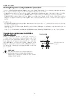
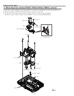
Mechanical Disassembly
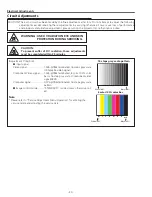
Fig.5
b
Power board, Fan(FN002) and Filter Ass'y removal
1. Remove the Power board spacer sheet.
2. Remove 8 screws A(M3x8) and 2 screws B(M4x6) to remove the Power box.
3. Remove the Filter Ass'y.
Power board
spacer sheet
A (M3x8)x8
A
A
A
A
A
A
A
Filter Ass'y
B
B(M4x6)x2
Power box bottom view
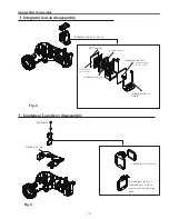
X3
Ballast
board
Ferrite core
Fix the ferrite
core here.
Power top holder
Power shield
TEMP spacer
shield
SW601
Power top
holder
FN002
Ballast board
(T3x8)x3
T3x8
Power
board
Label
side
Note:
Please pay attention to the install
direction of SW601, the side with
text facing to the projector back.
Power box
Summary of Contents for LC-XBM31
Page 67: ...67 IC Block Diagrams PW190 Scaler IC301 MR4010 Power OSC IC631...
Page 69: ...69 IC Block Diagrams TB6608FNG IRIS Control IC601 TLV320AIC3105 Audio Control IC5002...
Page 74: ...74 Parts Location Diagrams KT8 XBM3100 S03 L05 Relay out M03 Relay lens Out assembly...
Page 95: ...Key No Part No Description Key No Part No Description 95 Electrical Parts List KT8 XBM3100...
Page 96: ...KT8BE November 2010 Printed in Japan 2010 Eiki Internatinal Inc A key to better communications...


