background image

50

(Corner Keystone)


Top Left Corner 

PICTURE

PICTURE

Press  ▲▼◄►to  correct  top  left  corner 

image distortion.


X: -192~192


Y: 

-120~120    


Top Right Corner 

Press  ▲▼◄►to  correct  top  right  corner 

image distortion.

PICTURE

PICTURE


X: -192~192


Y: -120~120


Bottom Right Corner 

Press ▲▼◄►to bottom right corner image 

distortion.

PICTURE

PICTURE


X: -192~192


Y: -120~120


Bottom Left Corner 

Press ▲▼◄►to bottom left corner image 

distortion.

PICTURE

PICTURE


X: -192~192


Y: -120~120


Reset: 

Set all values to 0.

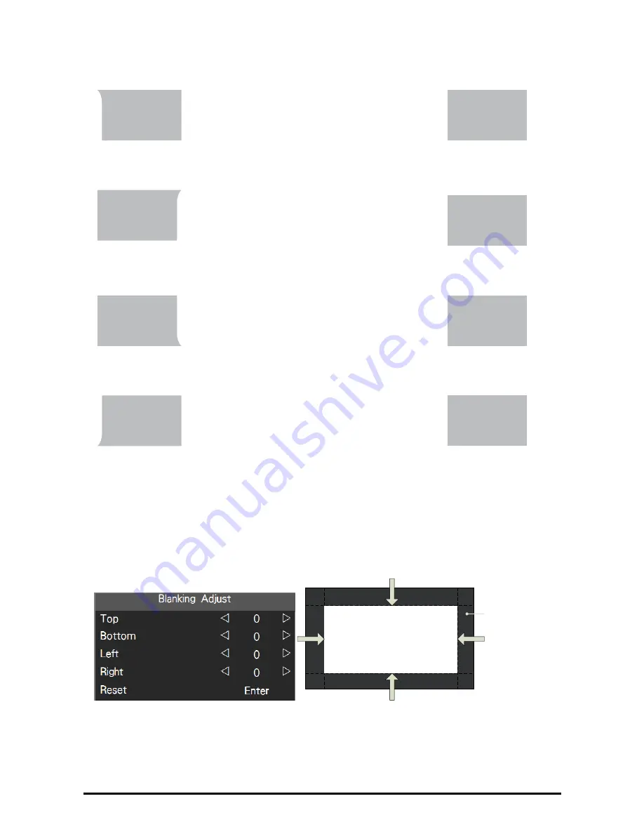
Blanking

Use this function to adjust the edges of the image and hide unwanted sections of the 

screen up to 30%.


%ODQNLQJ

$UHD

Summary of Contents for EIP-UJT100

Page 1: ...Multimedia Projector Model EIP UJT100 Owner s Manual Projection lens is optional E I P U J T 1 0 0 ...

Page 2: ... displays by overlapping projector images and blending the edges HDBaseT The projector can support Full HD uncom pressed video transmitting with HDBaseT Various Lamp Power Options The advanced dual lamp optical engine as well as the single lamp dual lamp Nor mal Eco energy saving and Custom Pow er Level mode offer the convenience for in stallation and maintenance Custom Power Level option allows y...

Page 3: ...ectors 15 Control Keys and LED Indicators 16 Control Keys 16 LED Indicators 16 Remote Control 17 Remote Control Battery Installation 18 Remote Control Receivers and Operation Range 19 Wired Remote Control 19 Installation 20 Lens Installation 20 Install and change the projector Lens 20 Remove Lens 21 Positioning Projector 22 Picture Level and Pitch Adjustment 22 Adjusting the Picture Orientation 22...

Page 4: ...39 Brightness 39 Sharpness 39 Noise Reduction 40 Color Temperature 40 Input Balance 40 Aspect Ratio 40 Timings 41 Auto Image 41 OSD Operation LAYOUT 42 Overscan 42 Main Select 43 PIP Select 43 PIP Position 44 PIP 44 OSD Introduction LAMPS 44 POWER 45 Mode 45 High Altitude 45 Custom Power Level 45 Lamp 1 Status 46 Lamp 2 Status 46 Lamp1 Run Time 46 Lamp2 Run Time 46 OSD Introduction ADVANCED 46 Rea...

Page 5: ...56 Signal Format 57 H V Refresh Rate 57 Lamp 1 Run Time 57 Lamp 2 Run Time 57 Lamp Hour Reset 57 Projector Run Time 57 Blue Only 57 Factory Reset 57 Maintenance and Care 58 Lamp Replacement 58 ORDER REPLACEMENT Lamp 59 Filters Replacement 60 ORDER REPLACEMENT Filter 61 Appendix 62 Technical Specification 62 Product Outline Dimension 63 Support Timing List 64 SDI Format 65 DVI dual link for 3D 65 P...

Page 6: ...ersiellen estpasmanipuleecorrectement Eteignez l appareil avant de changer la lampe Referez vous aux instructions donnees dans la section remplacement de lampes CAUTION CAUTION RISK OF ELECTRIC SHOCK DO NOT OPEN TO REDUCE THE RISK OF ELECTRIC SHOCK DO NOT REMOVE COVER OR BACK NO USER SERVICEABLE PARTS INSIDE EXCEPT LAMP REPLACEMENT REFER SERVICING TO QUALIFIED SERVICE PERSONNEL THIS SYMBOL INDICAT...

Page 7: ...illustrations indicates the re quired distance from the side walls and ceiling 70cm 50cm 50cm 30cm Do not cover the ventilation slots on the projector Heat buildup can reduce the service life of your projector and can also be dangerous If the projector is unused for an extended period of time unplug the projector from the power outlet CAUTION ON HANGING FROM THE CEILING When hanging the projector ...

Page 8: ...tor damaged If the provided plug does not match the outlet contact an electrician to change the old one Prevent the power cord from being treaded or pressed especially the power cord near the plug outlet and the connection between the power cord and the equipment Unplug the power cord during a lighting or when the equipment is not used for long peri ods Do not stare directly at the lens when the p...

Page 9: ...this area Can t tilt in this area Do not tilt the projector more than 10 degrees from side to side Not allow the projector in upward or downward the projection No Portrait Mode No Portrait Mode Do not put the projector on either side to project an image CAUTION ON CEILING MOUNTING For Ceiling mounting you need the ceiling mount kit designed for the projector When the projector is not mounted prope...

Page 10: ...ence to radio communications Operation of this equipment in a residential area is likely to cause harmful interference in which case the user will be required to correct the interference at his own expense Do not make any changes or modifications to the equipment unless otherwise specified in the instructions If such changes or modifications should be made you could be required to stop operation o...

Page 11: ...he pin face of the plug i e red or orange Fuse covers are available from the Parts De partment indicated in your User Instructions If the plug supplied is not suitable for your socket outlet it should be cut off and destroyed The end of the flexible cord should be suitably prepared and the correct plug fitted WARNING A PLUG WITH BARED FLEXIBLE CORD IS HAZARDOUS IF EN GAGED IN A LIVE SOCKET OUTLET ...

Page 12: ...he CD ROM Accessories List Owner s Manual CD EIP UJT100 EIP UJ T1 00 AC Power cord US Type 2 Euro Type 1 China Type 1 Remote control Batteries AA or LR6 1 3 2 4 1 5 ASPECT RATIO AUTO IMAGE PAUSE TEXT MENU SHARPN PHASE CONTRAST POWER INPUT ON OFF BRIGHTNESS ADDRESS SWAP PIP FOCUS FOCUS ZOOM ZOOM LENS CONTROL Quick start guide RoHS Card for China 铅 Pb 汞 Hg 镉 Cd 六价铬 Cr VI 多溴联苯 PBB 多溴二苯醚 PBDE 光机引擎 铝或铝...

Page 13: ... D23010 1 62 F 2 5 in center F 4 5 in corner 52 4 85 3 25 50 10 2 56 4 16 1 AH D23020 1 67 F 2 5 in center F 4 5 in corner 84 86 142 03 25 50 10 4 16 6 96 1 Projection Size and Distance Distance unit m Lens Type AH D22010 AH D22020 AH D22030 AH D21010 AH D23010 AH D23020 Inch Fixed Fixed Wide Tele Wide Tele Wide Tele Wide Tele 80 1 2 90 1 3 100 1 4 4 0 5 5 120 1 7 4 8 6 6 150 2 2 3 6 4 5 6 0 6 0 8...

Page 14: ...e Receiver Front Air Intake Vent Filter Cover AC Power Switch Terminals and Connectors Exhaust Vent Adjustable foot Power Cord Connector Lens Optional 4 5 6 1 7 7 2 3 Infrared Remote Receiver Rear Exhaust Vent and Lamp Cover 1 Exhaust Vent and Lamp Cover 2 Control Panel Filter Cover Air Intake Vent Adjustable foot ...

Page 15: ... connects to DVD HD DVD BD player HD set top box or other SD HD input source SYNC IN OUT IN From source equipment for informing which field of signal is the Left eye or Right eye signal OUT From projector and be connected to the 3D SYNC wireless transmitter for syn chronizing the projected picture with the 3D glasses LAN 10 100 BASE T Connect the Ethernet cable to the terminals for controlling the...

Page 16: ...D appears STANDBY LED Blue The indicator that shows the projector s standby status ON LED Green Displays the projector s power status ERROR LED Red Displays the cause of problem i e temperature fan lamp or system that has led to projector malfunction LED Indicators Standby Cooling Warm up Lamp fail Lamp door open Fan Fail Over Temperature System Errow Light on Blue Power on Normal Light on Green L...

Page 17: ... be able to operate the OSD Menu normally When TEXT is set to OFF only ON OFF 1 5 SWAP PIP PAUSE will function normally pressing any other buttons will not access the OSD Menu 9 AUTO IMAGE Resync the picture The adjustments also apply to PIP input 10 PAUSE SHUTTER Open Close the shutter 11 SHARPNESS Adjust picture sharpness and clarity 12 CONTRAST Adjust the picture contrast 13 BRIGHTNESS Adjust t...

Page 18: ...tallation 1 2 3 1 Slide the battery cover to remove it 2 Install two AA 2 batteries with the correct polarity 3 Put back the cover Note Make sure that the battery polarities are correct when installing the batteries Do not mix an old battery with a new one or different types of batteries Avoid contact with water or liquid Do not expose the remote control to moisture or heat Do not drop the remote ...

Page 19: ... Infrared Remote Receiver which is lo cated farther away from the fluorescent light Wired Remote Control The remote control can be used as a wired remote control Wired remote control helps you use the remote control outside the operating range Connect the remote control and the projector with the remote control cable supplied If the remote control is connected to the cable the remote control does ...

Page 20: ...on check where the projector is used and prepare a suitable lens For the details contact the sales dealer where you purchased the projector Install and change the projector Lens 1 Remove the sponge 2 Insert the lens and ensure the lens touches the lens holder Carefully the lens motor board must insert into the machine s jack ...

Page 21: ...21 3 Please confirm whether the lens is properly inserted Then rotate the lever counter clockwise to lock the lens Remove Lens 1 Rotate the lever clockwise to unlock the lens then take out the lens 1 2 ...

Page 22: ...sition the projector Ceiling Front Select this location with the projector mounted on the ceiling in front of the screen Ceiling mount kit is required Please consult your dealer for more details Rear Select this location with the pro jector placed behind the screen Note that a special rear projection screen is required Ceiling Rear Select this location with the projector mounted on the ceiling beh...

Page 23: ...right no more 8 Desk Front Projection Verticial Shift Up Verticial Shift Down Height of projected image Max 0 5V Max 0 25V Projected image height V Normal projection position Verticial Shift Up Verticial Shift Down Height of projected image Max 0 5V Max 0 25V Projected image height V Shift to Right Shift to Left Width of projected image 1H 0 1H 0 1H HD CONNECT LAN HDMI VGA G Y B Pb R Pr DVI Dual L...

Page 24: ...omation system to the RS 232 port on the projector Use a standard 9 pin serial cable wired straight through NOTE Accessories not including the cables of DVI BNC VGA HDMI and RS 232C HDMI IN VGA IN G Y B Pb R Pr DVI D IN H V RS 232C HDBaseT 1 2 R C IN 12V Trigger OUT Y Pb Pr IN OUT SYNC LAN IN OUT 3G SDI HDMI Cable BNC Cable VGA Cable Laptop computer Desktop Computer 24X DVD RW Signal Output DVI Ca...

Page 25: ...in Type A NOTE Accessories not including the cables of HDBaseT Video DVI SDI and HDMI Component Video Output B Pb G Y R Pr SDI Out HDMI Output Blu ray Player Component Video output equipment Such as high definition TV source HDMI IN VGA IN G Y B Pb R Pr DVI D IN H V RS 232C HDBaseT 1 2 R C IN 12V Trigger OUT Y Pb Pr IN OUT SYNC LAN IN OUT 3G SDI DVI Output ...

Page 26: ...ease connect such device equipment to the projector s 12V Trigger output as illustrated After you have done so your screen will lower automatically whenever you turn on your projector for your convenience Maximun 200mA for Trigger1 or 2 HDMI IN VGA IN G Y B Pb R Pr RS 232C HDBaseT 1 2 R C IN 12V Trigger OUT Y IN OUT 3G SDI ...

Page 27: ...b Pr IN OUT SYNC LAN IN OUT 3G SDI 3D Glasses IR Emitter LAN Connection If you want to control the projector via the internet web You can use LAN RJ 45 to con nect the computer server and projector Key in the correct IP Address or the computer host name which same as the projector s host name then you can remote control the projector by internet VGA IN G Y B Pb R Pr DVI D IN H V R C IN 12V Trigger...

Page 28: ... to wired remote controller You can use the remote control as a wired remote control HDMI IN VGA IN G Y B Pb R Pr RS 232C HDBaseT 1 2 R C IN 12V Trigger OUT Y Pb IN OUT 3G SDI Wired Remote cable length 5m 16 4 feet ...

Page 29: ...ocking the plug holder clamp To reduce the risk of electrical shock do not plug into any other type of power system If you are not sure of the type of power being supplied consult your authorized dealer or service center Connect the projector with all peripheral equipment before turning on the projector AC IN VOLTAGE SELECT Select 115V or 230V Note Unplug the AC power cord or turn off the MAIN ON ...

Page 30: ...HDMI RGBHV DVI VGA POWER INPUT ON OFF FOCUS FOCUS ZOOM LENS CONTROL 4 5 Turn Off the Projector 1 Press and hold the POWER button for 5 seconds on the side control or OFF button the remote control to turn off the projector 2 If the LAMP indicator lights bright and the POWER indicator turns off After the projec tor is turned off the cooling fans operate You cannot turn on the projector during this c...

Page 31: ...ult input setting and these setting are changeable Refer to Page 54 Button 1 5 ENTER INPUT STANDBY 3 2 1 HDBaseT HDMI RGBHV DVI VGA POWER INPUT ON OFF FOCUS FOCUS ZOOM LENS CONTROL 4 5 Selecting a Aspect Ratio Press ASPECT to adjust the aspect ratio of the image For detail information refer to Page 40 Aspect Ratio 1 3 2 1 ASPECT RATIO AUTO IMAGE HDBaseT HDMI RGBHV DVI VGA PAUSE TEXT MENU SHARPNESS...

Page 32: ...ress the MENU button to open the OSD 2 Press or to select a title menu 3 Press or to select an item The selected item will be highlighted 4 Press the Enter and or to change or adjust the selected item 5 Press the MENU in the monent move to upper menu ERROR MENU ON LED STATUS 1 3 2 1 ASPECT RATIO AUTO IMAGE RGBHV DVI PAUSE TEXT MENU SHARPNESS CONTRAST BRIGHTNESS FOCUS FOCUS ZOOM ZOOM LENS CONTROL 4...

Page 33: ...t can display the menus in English French Spanish German Portuguese Simplify Chinese Traditional Chinese Japanese or Korean Press the MENU to open the OSD Go to SYSTEM and select Language then press the Enter You can select a language there ...

Page 34: ...00 Sharpness 0 200 Noise Reduction 0 200 Color Temperature 3200K 5400K 6500K 9300K Native Input Balance Black Balance Offset Red Offset Green Offset Blue Offset White Balance Red Gain Green Gain Blue Gain Aspect Ratio 5 4 4 3 16 10 16 09 1 88 2 35 Letterbox Native Unscaled Timings H Total H Start H Phase V Start Auto Sync Execute LAYOUT Overscan Off Crop Zoom Main Select HDMI HDBaseT VGA Y Pb Pr R...

Page 35: ...COM SIM Test Pattern Color Bar Cross hatch Half scanning Red Green Blue White Black Red Green Blue Gray Scale Color Gamut Native EBU SMPTE Custom Main Menu Sub menu ADVANCED Custom Color Gamut Red x Red y Green x Green y Blue x Blue y Cyan x Cyan y Magenta x Magenta y Yellow x Yellow y White x White y Reset Center Lens Execute Warp Keystone Rotation Pincushion Barrel Top Left Corner Top Right Corn...

Page 36: ...GBHV Y Pb Pr 3G SDI 3D DVI Button 4 HDMI HDBaseT VGA Y Pb Pr RGBHV Y Pb Pr 3G SDI 3D DVI Main Menu Sub menu SYSTEM Button 5 HDMI HDBaseT VGA Y Pb Pr RGBHV Y Pb Pr 3G SDI 3D DVI Trigger 1 Auto 5 4 4 3 16 10 16 09 1 88 2 35 Letterbox Native Unscaled Trigger 2 Auto 5 4 4 3 16 10 16 09 1 88 2 35 Letterbox Native Unscaled Auto Source On Off Language English Français Español Deutsch Português 简体中文 繁體中文 ...

Page 37: ...ual link to connect to a stereo 3D source it is usually a computer with 3D Graphics card and 3D applications Below information is the DVI D 3D DVI format Signal Type Resolution Frame rate DVI single link DVI dual link 3D Reference PC 1920x 1080 120Hz V V 1920x 1080 100Hz V V 1920x1200 120Hz V V Reduced Blanking 1920x1200 100Hz V V Reduced Blanking 1920x 1080 60Hz V 1920x1200 60Hz V Reduced Blankin...

Page 38: ...the color space matrix to that defined in ITU R BT 601 RGB PC uses RGB color space and sets black at 0 0 0 RGB and white at 255 255 255 RGB assuming an 8 bit image RGB Video uses RGB color space and sets black at 16 16 16 RGB and white at 235 235 235 assuming an 8 bit image to correspond to the luminance values defined in digital component standards Input Locking Use this function to lock a source...

Page 39: ...ction is executed automatically when the input source is selected OSD Operation PICTURE Contrast Use or to adjust the contrast of the projected image Adjustable value 0 to 200 Note Brightness and Contrast controls are interactive The screen change to one may require a subtle change to the other in order to achieve the optimum setting Brightness Use or to adjust the level of black in the image to i...

Page 40: ...t Balance To adjust Black and White balance Black Balance Adjust R G B color offset of image that will control dark areas White Balance Adjust R G B color gain of image that will control bright areas Aspect Ratio This function allows user to adjust the picture s Aspect ratio When Native input is 16 10 the images as following is the result of picture s aspect ratio for your preference Aspect Ratio ...

Page 41: ...the picture still flicker or show noise i e edges on texts after optimization adjust phase accordingly V Start Use to adjust the projected picture s vertical position If the projected picture is not at the center of the screen i e shifted up or down and ends up being cropped use this function to adjust the picture s vertical position Down Up It is recommended that when adjusting the picture the ho...

Page 42: ...42 OSD Operation LAYOUT Overscan Some programs may display the edges of the image Use this function to hide the edge by choosing one of the following two options 5 4 4 3 16 10 16 9 Off Crop Zoom ...

Page 43: ...ub Main Source Main HDMI HDBaseT VGA Y Pb Pr RGBHV Y Pb Pr 3G SDI PIP SUB HDMI v v v HDBaseT v v v VGA v v v Y Pb Pr v v v RGBHV Y Pb Pr v v v 3G SDI v v v Note DVI D 3D DVI has not supported PIP PIP Select Press ENTER to display available sources for the sub picture then select a source Note that unavailable input source of sub menu are gray out and can not be selected The avail able input source...

Page 44: ...Bottom Right Split L R 1 2 Top Right PIP If you wish to display PIP picture you can make the configuration here By choosing ON you will see two windows on the projected picture the larger one is the primary pic ture and the smaller one is the sub picture By choosing OFF the PIP function will be dis abled and you will only see a single picture window OSD Introduction LAMPS ...

Page 45: ...occurs you can use this function to fine tune the brightness of the two projectors to achieve consistent pic ture brightness To access this function go to the OSD Menu LAMPS Power Custom Level Custom Power Level and adjust accordingly Note ECO is automatically selected between 35 40 C 95 104 F Mode Use or function to select single or dual lamp mode High Altitude Use this function to switch the pro...

Page 46: ...inform the user of Lamp1 s total run time Lamp2 Run Time This function is limited to display purposes to inform the user of Lamp2 s total run time Note You can choose to use one single lamp The projector will automatically determine the usage hours for lamp1 and lamp2 and choose the lamp with lower hours for the operation OSD Introduction ADVANCED ...

Page 47: ...Focus Press Enter button to switch window for Zoom Focus adjustment or Lens Shift adjustment Dynamic Contrast When activated this function the projector will dynamically adjust the picture contrast from the beginning of the projection until the content has ended Gamma You can choose from five different gamma settings 1 8 2 0 2 2 2 35 2 5 and Dicom sim on the projector to affect picture darker brig...

Page 48: ...the EBU color gamut it is primarily suited for input devices using PAL 576i 576p and so forth SMPTE Choose this to apply the SMPTE color gamut it is primarily suited for input devices using NTSC 480i 480p and so forth Custom Choose this to customize the color gamut as your preference through serial commands Custom Color Gamut This allows user adjust primaries Red Green Blue secondaries Cyan Yellow...

Page 49: ...ertical distortion The adjustable value H 350 300 V 32 32 Rotation Press or to rotate the projected image The adjustable value is from 20 to 20 P P P 20 20 0 Pincushion Barrel Use this function to correct pincushion or barrel distortion The adjustable range is from 100 to 100 steps Press to correct pincushion distortion to correct barrel distortion P P P 100 100 0 ...

Page 50: ...on PICTURE PICTURE X 192 192 Y 120 120 Bottom Right Corner Press to bottom right corner image distortion PICTURE PICTURE X 192 192 Y 120 120 Bottom Left Corner Press to bottom left corner image distortion PICTURE PICTURE X 192 192 Y 120 120 Reset Set all values to 0 Blanking Use this function to adjust the edges of the image and hide unwanted sections of the screen up to 30 ODQNLQJ UHD ...

Page 51: ...rlapped area boundary Press to adjust the white level at Top Bottom Left Right directions on the projected picture As shown in the below drawing the white level area is the overlap area of the projected picture 1 and the projected picture 2 The white level lines that is set where the other projector last pixels ends Black Level The outward boundaries of overlapping edges might appear brighter than...

Page 52: ...e Adjust black level of projector correspond ing to Image 1 to match the black level of inactive DMD display area of another projector And per forming the same adjustment on the projector corresponding to Image 2 Reset Set all the value to 0 Adjust Lines When the function is ON there will be adjust lines on the picture in order to easily adjust multiple pictures Press on the remote control to adju...

Page 53: ...he same re mote control just need to change the IR Address 1 or 2 Eco Network Power Selecting the ECO network disable the LAN function When this function set to ON the projector will turn off the power that control the the LAN board So you can t operate the projector remotely over a network at the standby mode If set to OFF you won t conserve power but can control the projector remotely over a net...

Page 54: ...ect to the projector via a web browser with the IP address shown on the OSD menu System Network Menu Position Set the OSD pop on the screen s position The default setting is Center Top Left Bottom Left Bottom Right Center Top Right Start Up Logo Use select on or off of the start up logo Start Up Chime Set it to On to have the projector play a sound effect during start up when it is set to off the ...

Page 55: ...Ratio is set to 16 10 16 9 Outputs 12V of power on Trigger when Aspect Ratio is set to 16 9 1 88 Outputs 12V of power on Trigger when Aspect Ratio is set to 1 88 2 35 Outputs 12V of power on Trigger when Aspect Ratio is set to 2 35 Letterbox Outputs 12V of power on Trigger when Aspect Ratio is set to Letterbox Native Outputs 12V of power on Trigger when Aspect Ratio is set to Native Unscaled Outpu...

Page 56: ...iming files will be erased in the Factory Reset operation Model The designated model number of the projector Serial Number The designated serial number of the projector Software Version The version of software installed on the projector Active PIP Source Displays the current Active PIP sources Pixel Clock Displays the pixel clock of the current input signal ...

Page 57: ...hours to ensure the accuracy of lamp hours dis played in the OSD Menu Projector Run Time Displays the projector s total operating hours Blue Only This function displays only blue color to facilitate the process of image inspection for a service personnel Factory Reset Restore the configurations in the OSD Menu back to the factory default Note that this function will not apply to items including no...

Page 58: ... the projector for approximately 30 minutes to cool enough before removing the lamp module for replacement Note When you turn off the projector the lamp inside the projector will still be very hot approximately 200 300 C If you attempt to replace the lamp without allowing the projector to cool you could risk scald ing yourself This is why you should wait for no less than 30minutes for the lamp to ...

Page 59: ... Install the lamp units and tighten the screws on them 8 Reconnect power to the projector and reset the lamp usage timer Refer to Page 46 Lamp1 Run Time Page 46 Lamp2 Run Time ORDER REPLACEMENT Lamp Replacement Lamp can be ordered through your dealer When ordering a lamp give following information to the dealer Replacement lamp P N AH D31010 ...

Page 60: ...er may reduce the air flowing into the projector and the temperature in the projector may rise as a result This may activate the protection mechanism or damage the components Suggest to change the filter each 2000 hours Check clean and replace the filter periodically 1 Loosen the screws on the filter cover 2 Remove the filter cover and take out the old filters ...

Page 61: ...e x White side x 3243411700 3243270701 4 Tighten the screws on the filter cover ORDER REPLACEMENT Filter Replacement filter can be ordered through your dealer When ordering a filter give following information to the dealer Replacement Filter P N 3243270701 Rear 3243411700 Front ...

Page 62: ...ection Ports HDMIx1 RGB H Vx1 YPbPrx1 VGAx1 DVI Dx1 SDIx1 HDBaseTx1 SYNC INx1 SYNC OutX1 R C INx1 12V Triggerx2 RS 232x1 LANx1 Projection Method Table Top Ceiling Mount Front or Rear Dimensions W x D x W 550x505x250mm 21 7 x19 9 x9 8 Weight Without Lens 37kg 81 4lbs Power Supply AC 100 240V 50 60Hz Power Consumption Input Voltage Normal Mode ECO Mode 220V 1140W 895W 110V 1230W 955W Standby 5W LAN ...

Page 63: ...99 8 220 105 160 633 4 Mounting bracket screw hole M6 These screw holes are used to mount the projector to its designated mounting bracket using 6 M6x15 screws The dimensions of the screw holes are shown in the picture below EIP UJT100 ...

Page 64: ...x900 60 V V 1280x768 60 V V 1280x800 60 V V 1280x960 60 V V Apple Mac 640x480 66 59 V V 832x624 74 54 V V NTSC NTSC M 4 43 59 94 PAL PAL B G H I 50 PAL N 50 PAL M 59 94 SECAM SECAM M 50 SDTV RGBS 50 480i 59 94 V V 1440x480i 60 V V V V 1440x576i 50 V V V V 576i 50 V V EDTV 480p 59 94 V V V V V V V V 576p 50 V V V V V V V V HDTV 1035i 60 V V V V V V V V V 1080i 50 V V V V V V V V V 1080i Aus 50 V V ...

Page 65: ...CbCr 4 2 2 10 720P50 HD SMPTE 292M 1 5Gbps HD YCbCr 4 2 2 10 1080Sf25 HD SMPTE 292M 1 5Gbps HD YCbCr 4 2 2 10 1080Sf30 HD SMPTE 292M 1 5Gbps HD YCbCr 4 2 2 10 1080P50 3G Level A SMPTE 424M 3Gbps YCbCr 4 2 2 10 1080P59 3G Level A SMPTE 424M 3Gbps YCbCr 4 2 2 10 1080P60 3G Level A SMPTE 424M 3Gbps YCbCr 4 2 2 10 1080P50 3G Level B SMPTE 424M 3Gbps YCbCr 4 2 2 10 1080P59 3G Level B SMPTE 424M 3Gbps Y...

Page 66: ...or is 192 168 0 100 please follow below steps to set the network configuration Connect RJ 45 cable from PC to the LAN connector on the projector HDMI IN VGA IN G Y B Pb R Pr DVI D IN H V RS 232C 1 2 R C IN 12V Trigger OUT Y Pb Pr IN OUT SYNC LAN 2 Set up Internet Protocol TCP IP Properties in your PC as below Recommended PC setting IP Address 192 168 0 99 Subnet 255 255 255 0 Default settings for ...

Page 67: ...d subnet mask and click SAVE to confirm the configuration Projec tor Web Control will show below message for confirmation The projector IP will be changed and the connection to the projector will be lost do you want to continue Select Yes to confirm the changes No to cancel Note Make sure the IP address of the projector and PC are in the same network group ...

Page 68: ...wer on off source etc Note If projector control option is selected to RS232 the web control will be interrupt Network control has to be enabled from the projector s OSD menu before connecting to projector web control Image Setting Click arrows to adjust the image settings such as Brightness Sharpness etc on the web page ...

Page 69: ...trol the projector by the remote control or control panel on the projector click arrows to adjust the settings Geometry Adjust Click the arrow buttons to adjust Blanking Warp Four Corner and click the option to select the aspect ratio setting Click Reset option to reset Blanking or Warp to the default setting ...

Page 70: ... other options are unavailable and N A is shown on the column The other options are available only when Edge Blend is enabled Advance Control This page allows you to select color temperature or adjust black balance or white balance Click the option to select Color Temp or arrow button to adjust the setting ...

Page 71: ...fferent value If the network provides DHCP service you can enable DHCP client IP Address Subnet and Gateway will be assigned by DHCP service Please contact with your network administration for more details Diagnostics Advance Diagnostics This page is to diagnose the projector Okay is displayed under normal condition Error code is displayed if there is an error in the projector If any abnormal code...

Page 72: ...72 About This page shows the product input source lamp installation information etc Remote Emulator Operate the projector with the remote control illustrated in the browser as actual one ...

Page 73: ... SCL 6 T M D S Data 1 Input 16 SDA 7 T M D S Data 0 Input 17 Ground 8 Ground 18 P5V 9 T M D S Data 0 Input 19 HPD 10 T M D S Clock C Input DVI D 9 1011 1213141516 1819 2021222324 17 1 2 3 4 5 6 7 8 1 T M D S Data 2 Input 13 N C 2 T M D S Data 2 Input 14 P5V 3 Ground 15 Ground 4 N C 16 HPD 5 N C 17 T M D S Data 0 Input 6 SCL 18 T M D S Data 0 Input 7 SDA 19 Ground 8 N C 20 N C 9 T M D S Data 1 Inpu...

Page 74: ... HDBaseT 8 7 6 5 4 3 2 1 1 TX 2 TX 3 TXC 4 Ground 5 Ground 6 RXC 7 RX 8 RX Screen Trigger Tip Sleeve Ring 1 Tip VCC 12V 2 Sleeve Ground 3 Ring Signal Wired Remote Tip Sleeve Ring 1 Tip VCC 3 3V 2 Sleeve Ground 3 Ring Signal ...

Page 75: ...t 2 Midland ON L4R 4K8 Canada Tel 1 800 563 3454 1 705 527 4084 Fax 1 800 567 4069 1 705 527 4087 E Mail canada eiki com Japan Worldwide EIKI Industrial Company Limited 6 23 Teramoto Itami shi Hyogo 664 0026 Japan Tel 81 72 782 7492 Fax 81 72 781 5435 Eastern Europe EIKI CZECH SPOL s r o Nad Cementárnou 1163 4a Praha 4 Podolí 147 00 Czech Republic Tel 420 241 410 928 420 241 403 095 Fax 420 241 40...

Reviews: