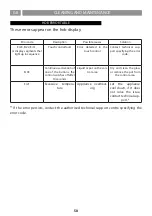
ANWEISUNGEN
D
38
WARNINGS
GB
38
C
leaning and maintenance must not be carried out by children without proper supervision.
I
f the power cord is damaged, it must be replaced by a qualified service centre or technician only.
C
AUTION: The hob protection devices must be only those designed by the appliance manufacturer
or those indicated as suitable in the manufacturers instructions or the hob protection devices
incorporated in the appliance.
The use of inappropriate protection devices may provoke accidents.
D
uring the installation the equipment must be connected to a power source whose system
impedance is matched to a value of 0.005+j0.005[Ohm].
D
o not seal the area between the glass and the worktop with silicone because should the cooktop
need to be replaced, the glass could break during removal.
T
he unit’s installation and electrical connection to the power grid must be carried out by qualified
service technicians only. The device’s electrical safety can be guaranteed solely if a regular ground
connection is provided for the cooking top. If in doubt, have the electrical system checked by
a qualified electrician. Do not connect the cooking top to the mains using extension cords or
multiple sockets, since they will not guarantee the required safety (e.g. risk of overheating).
Prior to connecting the cooktop, compare the connection specifications (voltage and fre quency)
indicated on the unit’s identification nameplate with those of the mains electricity supply.
These specifications must absolutely correspond, otherwise the unit may be subject to damage.
Contact an electrician if in doubt.
D
isconnect the unit from the mains when carrying out installation work, maintenance or repairs.
C
omply with all air discharge regulations.
C
AUTION: If the surface is cracked, switch off the appliance to avoid the possibility of electric
shock.
N
ever open unit’s outer casing. Any contact with live parts or the modification of electrical or
mechanical parts can cause operating abnormalities.
Summary of Contents for 5803
Page 2: ...2 ...
Page 4: ...r 5 800 515 474 759 220 214 173 4 ...
Page 5: ...5 600 480 222 50 300 100 c c ...
Page 6: ...6 480 760 r 5 5 5 50 760 804 2 0 2 0 519 480 2 0 2 2 MAX r5 r5 B B sez B B ...
Page 7: ... 7 ...
Page 8: ... 8 ...
Page 9: ... 9 ...
Page 10: ... 10 ...
Page 11: ... 11 ...
Page 12: ... 12 ...
Page 13: ... 13 ...
Page 14: ... 14 ...
Page 15: ... 15 ...
Page 16: ... 16 ...
Page 17: ... 17 ...
Page 18: ...18 ...
Page 19: ...19 ...
Page 20: ... 20 ...
Page 21: ... 21 ...
Page 22: ... 22 ...
Page 23: ... 23 ...
Page 24: ... 24 ...
Page 25: ... 25 ...
Page 26: ...26 ...
Page 27: ... 27 ...
Page 28: ... 28 ...
Page 29: ... 29 ...
Page 30: ... 30 ...
Page 31: ...31 ...
Page 32: ...32 ...
Page 33: ...33 ...
Page 34: ...34 ...
Page 35: ... 35 ...
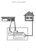
Page 36: ...36 Electrical connection diagram ...
Page 103: ...103 ...
Page 104: ...AFLIASPCB4OB01 Ed 16 04 20 ...


