14
B. Measuring Insulation Resistance
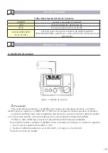
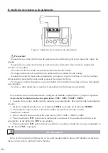
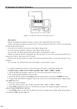
Figure 3. Insulation Resistance Measurement
Caution!
- When measuring insulation resistance, please must separate the two test leads.
- When performing insulation resistance tests, remove all power from the circuit to be measured
and discharge all the power.
- Do not short circuit two test leads under high voltage status.
- Do not measure insulation resistance after high voltage output.
- Do not carry out measurement when the battery compartment is open.
- When the measurement is completed, do not touch the circuit as the circuit has already stored
capacitance, which may cause electric shock.
- Don’t touch the test leads even after it has been removed from the circuit until voltages are all
released.
- Do not carry out measurement when the battery compartment is open.
To measure insulation resistance, set up the Meter as Figure 3 and do the following:
- Turn the rotary switch to one of these position 250V / 500V / 1000V / 2500V.
1. When performing insulation resistance tests, remove all power from the circuit
to be measured and discharge all the power.
2. Insert the red test lead into the
LINE
terminal and the black test lead into
EARTH
terminal.
3. Connect the red and black alligator clip to the circuit to be measured, positive voltage output
from
LINE
terminal.
- Continuous Measurement
1. Turn the rotary switch to one of these position 250V / 500V / 1000V / 2500V
2. Press
TEST
to button to carry out continuous measurement. Output insulation resistance
testing voltage,
TEST
button light up,
3. Press
TEST
button to close the insulation resistance measurement voltage when measurement
is completed.
TEST
button lights off.


