12
THE METER STRUCTURE
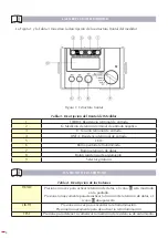
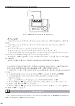
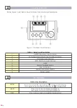
Below Figure 1 and Table 3 shows the Meter front structure and description.
Figure 1. The Meter Front Structure
Table 3. Meter Front Description
1
EARTH: Resistance input terminal
2
G: Voltage Measurement input negative terminal
3
V: Voltage input terminal
4
LINE: Resistance input terminal
5
LCD
6
Display Backlight button
7
Data Hold button
8
Insulation Resistance Button
9
Rotary switch
KEY FUNCTIONS
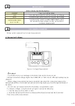
Table 4. Key Description
HOLD
Press once to turn the data hold on, is shown on the display
Press again to turn the data hold feature off. is disappeared
LIGHT
Press once to turn the display backlight on
Press again to turn the display backlight off
TEST
Press to stop or start an insulation resistance test


