Mechanical Operation and Maintenance Manual for ER180-4-3200 Industrial Robot
30
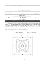
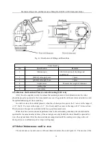
Fig. 4-1 Distribution of Filling and Drain Ports
Tools Needed
No.
Specification
Remarks
1
lubricant gun
with the function of checking and
counting oil
2
[M10x1] oil supply joint
1 piece
3
[φ8x1m] oil supply hose
1 piece
4
weight meter
Measure the weight of lubricant
5
sealing tape
/
6
gas source
/
4.4.4 Release the Residual Pressure in Lubricating Oil Cavity
After the oil is supplied, in order to release the residual pressure in the lubrication tank, the robot
should be properly operated. At this time, install a recovery bag under the lubricant inlet and outlet to avoid
the spilled lubricating oil from scattering.
In order to release the residual pressure, when the oil drain port is opened, the J1 axis is in the range of
± 30 °, the J2 / J3 axis is in the range of ± 5 °, the J4 axis and J6 axis are in the range of 30 ° for more than
20 minutes, and the speed is controlled in the low-speed movement state.
When the above actions cannot be performed due to the surrounding conditions, the robot should be
operated for the same number of times (if the axis angle can only be half, the robot should be operated for
twice the original time). After the above actions are completed, install the sealing screw plug on the oil
drain port (use a combination pad or wrap a sealing tape).
4.5
Robot Maintenance and Use Area
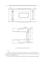
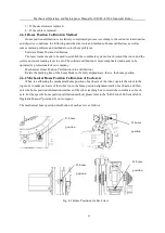
The maintenance area and use area of the mechanical unit are shown in Figure 4-2. The use area of the
J3 oil filling port


