


Schmid & Wezel
Seite / Page
35 / 53
Ausführung / Version
02 / 2011
5.2 Changing the rotor blades
For illustrations, refer to the compressed air
motor explosion drawing in Chapter "List of
spare and wear parts“.
•
Loosen the clamping ring, a/f 41 (right-hand
thread); ATTENTION: SK16-8DR => Left-
hand thread and unscrew the valve
housing.
•
Remove the compressed air motor from the
sleeve, clamp the rear plate in the extractor
tool and force out the rotor spindle.
•
Clean the parts and apply a little special oil.
•
Insert the new rotor blades.
•
Assemble in the reverse sequence.
•
Force in the axle bearing with an assembly
plug. Slide the compressed air motor in the
sleeve. Pay attention to the position of the
lever.
•
Clamping ring tightening torque = 30 Nm
5.3 Gear
head
maintenance
For illustrations, refer to the various explosion
drawings in Chapter "Spare and wear parts".
•
Remove the saw blade and protective
guard completely.
•
Remove the 3 screws.
•
Disassemble the tool spindle assembly out
of the gearbox by tapping lightly with a
plastic mallet.
•
Clean the parts and apply a little special
grease.
•
Clean the gear with petroleum ether and
apply a little special grease.
•
Check the needle bearing and sealing
shims for signs of wear; replace them with
original parts, if necessary.
•
Assemble in the reverse sequence.
Caution:
Do not forget the adjusting washers during
assembly!
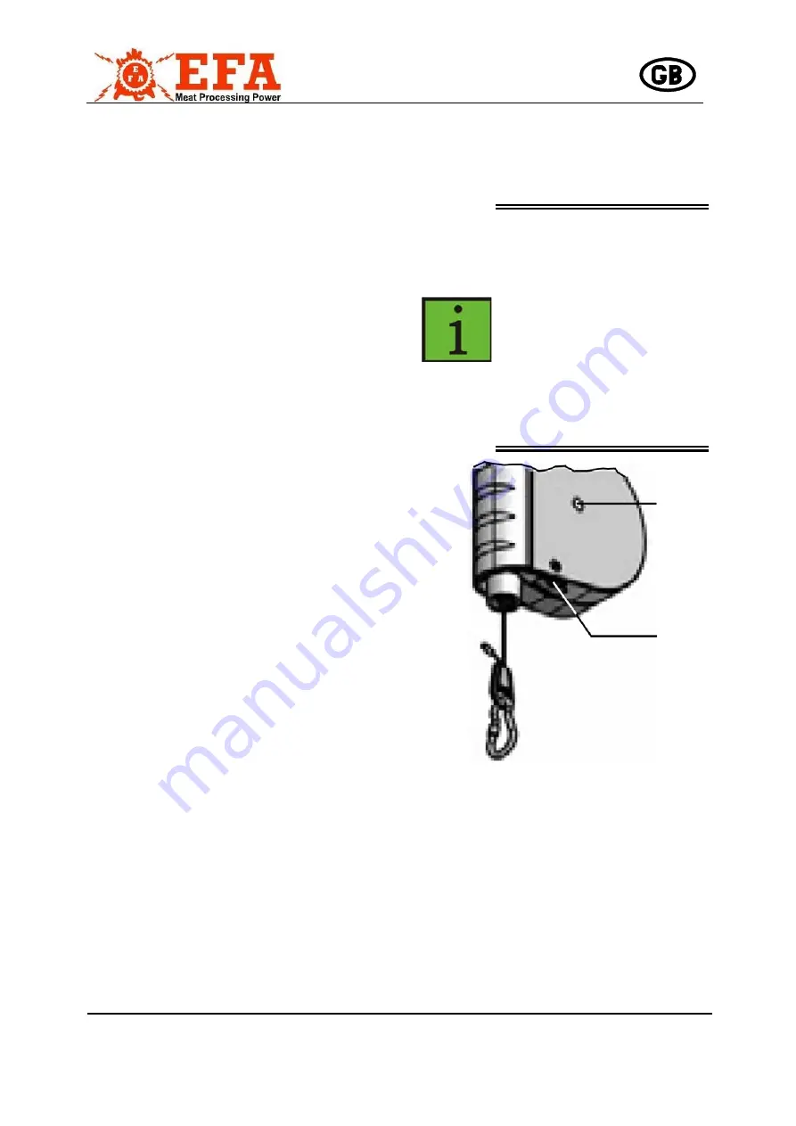
5.4 Adjusting the spring balancer
The spring balancers can be finely adjusted
using the adjusting screw (2) on the housing
(see Fig.).
Before adjusting the bearing
load, attach the load with the
rope fully pulled in.
Adjustment in direction "Plus"
(+) increases the bearing load.
Adjustment in direction
"Minus" (-) reduces the
bearing load.
The correct setting is achieved
when the attached load can be
pulled easily to the required
position and, on releasing it,
returns to its initial position.
Fig. 6:
Spring balancer
Insert the Allen key in the adjusting screw (2).
Use the Allen key to set the required setting
within the permissible adjusting range. The
adjusting screw (2) acts on the spring catch (1)
which is provided with a marking on the
outside. The adjustment can be observed
according to this marking.
1
2