Pagina
5 di 24
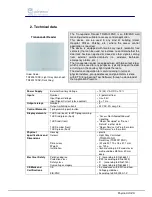
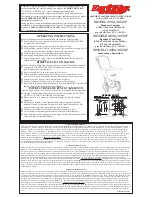
2.1 Wiring Diagram
2.2 Operating and display elements
2.3 Dimension drawing
Connections:
1 Power Supply 12/24 Vcc/ac
2 Power Supply 12/24 Vcc/ac
3 OUT 1 terminal relay 1 (NO)
4 OUT2 terminal relay2 (NO)
5 COM Outputs
6 IN 1 (potential free)
7 IN 2 (potential free)
8 COM Inputs
11 Bus Connection Terminal:
Black = bus polarity (-)
Red = bus polarity (+)
Operating Elements:
9 Programming LED
10 Programming push button
12 Led 4
13 Led 3
14 Led 2
15 Led 1
1
2
3
4
5
6
7
8
KNX
9
10
(11)
Input
2
Out 2
Input
1
Interfaccia BUS
KNX / EIB
Com
5
6
7
8
Com
Bassa tensione
max. 60 V ac/dc 2A
Alimentazione
12/24 V ac/dc
Out 1
1
2
4
3


