Pulse Pool Pump Installation & Operating Instructions – Part # 10-0030 Nov 2012
Page 3
General
The Pulse series pool pump has been specifically designed to operate todays swimming pools, its
high performance and high head flow characteristics will ensure that the Pulse pool pump will
operate with all your ancillary equipment including chlorinators, heaters, in floor cleaners and pool
cleaners.
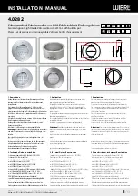
Installation of the Pulse Pool Pump
Edgetec Systems Pty Ltd has applied the latest CAD design software in designing your Pulse Pool
Pump to ensure that you have many years of trouble free operation. Here are some simple
installation rules that should be followed when installing the Pulse pool pump;
1.
Care should be taken to position the pump so that it has adequate drainage. Ensure the
motor cannot become wet or flooded and the pump location should be well ventilated.
The pump should be protected from direct sunlight and weather.
2.
Ensure that the pump is secured onto a stable base. The pump mounting foot has
mounting points where the pump can to be bolted to the base to prevent movement.
3.
The pump foot has an anti-vibration pad moulded into the base to minimise noise and
vibration. Failure to secure the pump to the base securely may cause damage and void the
warranty.
4.
The pump must be accessible for maintenance and be easily removed for service. Ensure
that you allow enough area around the hair and lint pot basket for removal and cleaning.
5.
The pump suction line requires a minimum of 50mm PVC pipe and should be kept as short
as possible with the minimum number of elbows and bends
and no air trap
for optimum
performance. The suction line must be installed below the water level until just in front of
the pump location and the vertical riser used to reach the pump inlet.
Note: Wear
protective gloves when using PVC glue and solvents and always allow 24 hours to dry
before starting the pool pump.
6.
The suction and return pipe work should be self-supported so that no strain from the
pipework loads up the pump barrel unions. The pump should not be suspended by the
pipe work or other equipment as this will cause leaks and eventual damage to the pump.
Only use the barrel unions supplied with the pump, barrel unions only require to be hand
tight,
do not use tools to tighten the barrel union nuts.
7.
If the pump is installed below the water level - isolation valves must be fitted to the
suction and return lines.
8.
Pump installations that are 500mm or more above the water level will require a foot valve
at the pool or a check valve in the suction line.
9.
Water temperature must not exceed 45°.