


12
The Panel Connectors
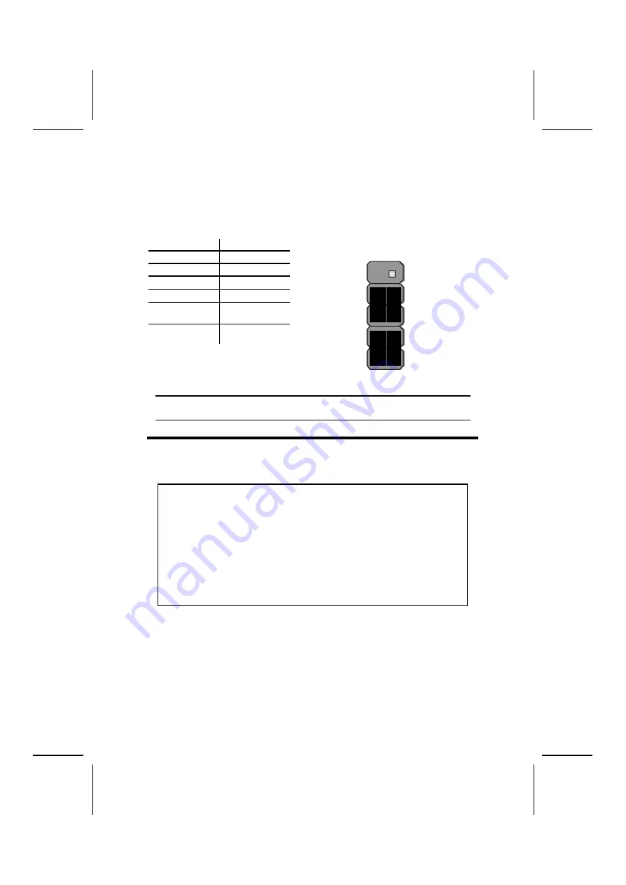
The panel connectors provide a standard set of switch and LED connectors
commonly found on ATX or micro-ATX cases. Refer to the table below for
information:
PANEL1
Device
Pins
Empty
10
N/C
9
Power ON/OFF
6, 8
Reset Switch
5, 7
Green LED
Indicator
+2, -4
HDD LED
+1, -3
H D D L E D
(Pins 1, 3)
2 1
R e s e t S w i t c h
(Pins 5, 7)
P o w e r S w i t c h
(Pins 6, 8)
G r e e n L E D
(Pins 2, 4)
Empty
( P i n 1 0 )
1 0 9
N / C
(Pin 9)
Note:
The plus sign (+) indicates a pin which must be connected to a positive
voltage.
I
I
n
n
s
s
t
t
a
a
l
l
l
l
i
i
n
n
g
g
H
H
a
a
r
r
d
d
w
w
a
a
r
r
e
e
Installing the Processor
Caution: When installing a CPU heats ink and cooling fan make sure that
you DO NOT scratch the mainboard or any of the surface -mount resistors
with the clip of the cooling fan. If the clip of the cooling fan scrapes
across the mainboard, you may cause serious damage to the mainboard
or its components.
On most mainboards, there are small surface -mount resistors near the
processor socket, which may be damaged if the cooling fan is carelessly
installed.
Avoid using cooling fans with sharp edges on the fan casing and the
clips. Also, install the cooling fan in a well-lit work area so that you can
clearly see the mainboard and processor socket.
Before installing the Processor
This mainboard automatically determines the CPU clock frequency and sys-
tem bus frequency for the processor. You may be able to change these
automatic settings by making changes to jumpers on the mainboard, or
changing the settings in the system Setup Utility. We strongly recommend that
you do not overclock processors or other components to run faster than their
rated speed.