background image

43

Using the Motherboard Software

Chapter 4
Using the Motherboard Software

The Auto-install CD-ROM makes it easy for you to install the drivers and software
for your motherboard.

If the Auto-install CD-ROM does not work on your system, you can still
install drivers through the file manager for your OS (for example, Win-
dows Explorer). Refer to the Utility Folder Installation Notes later in this
chapter.

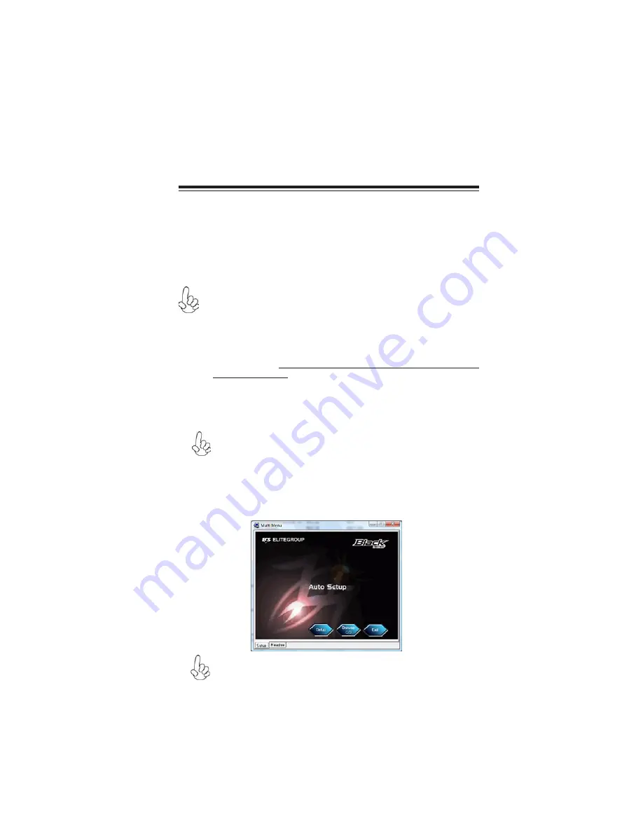
The support software CD-ROM disc loads automatically under Windows XP/Vista.
When you insert the CD-ROM disc in the CD-ROM drive, the autorun feature will
automatically bring up the install screen. The screen has three buttons on it, Setup,
Browse CD and Exit.

If the opening screen does not appear; double-click the file “setup.exe”
in the root directory.

About the Software CD-ROM

The support software CD-ROM that is included in the motherboard package contains
all the drivers and utility programs needed to properly run the bundled products.
Below you can find a brief description of each software program, and the location for
your motherboard version. More information on some programs is available in a
README file, located in the same directory as the software. Before installing any
software, always inspect the folder for files named README.TXT, INSTALL.TXT,
or something similar. These files may contain important information that is not
included in this manual.

Never try to install all software from folder that is not specified for use with
your motherboard.

The notice of Intel HD audio installation (optional):


The Intel High

Definition audio functionality unexpectedly quits working in Windows Server
2003 Service Pack 1 or Windows XP Professional x64 Edition. Users need
to download and install the update packages from the Microsoft Download
Center “before” installing HD audio driver bundled in the Driver CD.
Please log on to http://support.microsoft.com/default.aspx?scid=kb;en-
us;901105#appliesto for more information.

1.

2.

Auto-installing under Windows XP/Vista

Summary of Contents for A790GXM-AD3

Page 1: ......

Page 2: ......

Page 3: ...cy energy and if not installed and used in accordance with the instructions may cause harmful inter ference to radio communications However there is no guarantee that interference will not occur in a...

Page 4: ...le mat riel brouilieur du Canada AbouttheManual The manual consists of the following Describes features of the motherboard Go to H page 1 Describes installation of motherboard components Go to H page...

Page 5: ...lling the Motherboard in a Case 7 InstallingHardware 9 Installing the Processor 9 Installing Memory Modules 10 Expansion Slots 13 Connecting Optional Devices 15 Installing a Hard Disk Drive CD ROM SAT...

Page 6: ...ingtheMotherboardSoftware 43 About the Software CD ROM 43 Auto installing under Windows XP Vista 43 Running Setup 44 Manual Installation 48 Utility Software Reference 48 HDMIAudiosettingSOP 49 Chapter...

Page 7: ...compli ant to the PCI Express Gen2 version 2 0 The SB750 Southbridge supports two PCI slots which are PCI v2 3 compliant In addition two PCI Express x1 slots are supported fully compliant to the PCI...

Page 8: ...ost initiated power Man agement DIIPM HIPM Integrated USB 2 0 Host Controller supporting up to twelve USB 2 0 ports Integrated IDE controller supports Ultra ATA 133 100 66 33 modes Provides AMD SATA R...

Page 9: ...066 800 DDR3 SDRAM with Dual channel architecture Accommodates four unbuffered DIMMs Up to 8 GB per DIMM with maximum memory size up to 32 GB Audio 1 Some hardware specifications and software items ar...

Page 10: ...4 IntroducingtheMotherboard Motherboard Components The above image is for reference only please take the actual motherboard for detailed parts...

Page 11: ...ower on button 9 PANEL Front Panel switch LED header 10 SPK Internal speaker header 11 RST_BTN Reset button 12 IDE Primary IDE connector 13 F_USB1 3 Front Panel USB headers 14 SPDIFO SPDIF out header...

Page 12: ...6 IntroducingtheMotherboard Memo...

Page 13: ...case Make sure that your case supports all the features required Secondly this motherboard supports two enhanced IDE drives Make sure that your case has sufficient power and space for all drives that...

Page 14: ...8 InstallingtheMotherboard Do not over tighten the screws as this can stress the motherboard...

Page 15: ...or socket which may be damaged if the cooling fan is carelessly installed Avoid using cooling fans with sharp edges on the fan casing and the clips Also install the cooling fan in a well lit work area...

Page 16: ...CPU fan and heatsink installation procedures may vary with the type of CPU fan heatsink sup plied The form and size of fan heatsink may also vary Installing Memory Modules This motherboard accommodate...

Page 17: ...ge connector match the notches in the DIMM slot 5 Install the DIMM module into the slot and press it firmly down until it seats correctly The slot latches are levered upwards and latch on to the edges...

Page 18: ...ngston KVR1066D3N7 Micron MT8JTF12864AY 1G1D1 IMSH1GU03A1F1C 10G B2S81427034 IMSH1GU03A1F1C 10F B2S81427023 Samsung Gold Bar M378B2873DZ1 CF8 0818 Winchip 64A0TPHN8G17E Elixir M2F2G64CB8HA4N BE 0831 T...

Page 19: ...nt Interconnect and is a bus stan dard for expansion cards which for the most part is a supple ment of the older ISA bus standard The PCI slots on this board are PCI v2 3 compliant Before installing a...

Page 20: ...o use 2 Install the edge connector of the add on card into the expansion slot Ensure that the edge connector is correctly seated in the slot 3 Secure the metal bracket of the card to the system case w...

Page 21: ...connectors are used to support the new Serial ATA devices for the highest data transfer rates 3 0 Gb s simpler disk drive cabling and easier PC assembly It elimi nates limitations of the current Paral...

Page 22: ...tive Signal 5 USB_FP_P0 USB Port 0 Positive Signal 6 USB_FP_P1 USB Port 1 Positive Signal 7 GND Ground 8 GND Ground 9 Key Nopin 10 USB_FP_OC0 Overcurrent signal Function Pin Signal Name SPDIFO SPDIF o...

Page 23: ...r to the IDE device user s manual Installing two IDE devices on one cable ensure that one device is set to MASTER and the other device is set to SLAVE The documentation of your IDE device explains how...

Page 24: ...nstallation This motherboard supports the Hot Plug function 1 Attach either cable end to the connector on the motherboard 2 Attach the other cable end to the SATA hard drive 3 Attach the SATA power ca...

Page 25: ...rial ATA port multiplier Audio Ports Use the audio jacks to connect audio devices The C port is for stereo line in signal while the E port is for microphone in signal This motherboard supports audio d...

Page 26: ...er cable The ATX 24 pin connector allows you to connect to ATX v2 x power supply 1 Connect the CPU cooling fan cable to CPU_FAN 2 Connect the standard power supply connector to ATX_POWER 3 Connect the...

Page 27: ...or is used to provide power to the CPU ATX_POWER ATX 24 pin Power Connector 1 3 3V 13 3 3V 2 3 3V 14 12V 3 Ground 15 COM 4 5V 16 PS_ON 5 Ground 17 COM 6 5V 18 COM 7 Ground 19 COM 8 PWRGD 20 5V 9 5VSB...

Page 28: ...n ATX power cable to ATX4P otherwise the system will be unstable ATX12V ATX 12V Power Connector Pin Signal Name 4 Ground 3 Ground 2 Ground 1 Ground Pin Signal Name 5 12V 6 12V 7 12V 8 12V SPK Internal...

Page 29: ...Reset Switch Supporting the reset function requires connecting pins 5 and 7 to a momentary contact switch that is normally open When the switch is closed the board resets and runs POST Power Sleep Mes...

Page 30: ...24 InstallingtheMotherboard Memo...

Page 31: ...ures The settings made in the Setup Utility affect how the computer performs Before using the Setup Utility ensure that you understand the Setup Utility options This chapter provides explanations for...

Page 32: ...urrent menu Using BIOS When you start the Setup Utility the main menu appears The main menu of the Setup Utility displays a list of the options that are available A highlight indicates which option is...

Page 33: ...nel CMOS Setup Utility Copyright C 1985 2005 American Megatrends Inc IDE Master Help Item Select the type of the device connected to the system For the purpose of better product maintenance the manufa...

Page 34: ...rity for compatible IDE devices S M A R T Auto The S M A R T Self Monitoring Analysis and Reporting Technology system is a diagnostics technology that monitors and predicts device performance S M A R...

Page 35: ...t C 1985 2005 American Megatrends Inc Advanced Setup Enable disablethe generation of ACPI _PPC _PSS and _PCI objects Help Item AMD C Q Enabled Enhanced Halt C1E Disabled Quick Power on SelfTest Enable...

Page 36: ...pyright C 1985 2005 American Megatrends Inc Hard Disk Drives Press Esc to return to the Advanced Setup page F10 Save ESC Exit Value Enter Select F9 Optimized Defaults F1 General Help Move Boot Other D...

Page 37: ...mode DRAM Controller mode Options Disabled UMA CMOS Setup Utility Copyright C 1985 2005 American Megatrends Inc Advanced Chipset Setup Internal Graphics Mode UMA GFX Clock Override Disabled Share Memo...

Page 38: ...o return to the main menu setting page USB Functions Enabled Use this item to enable or disable the USB function Legacy USB Support Enabled Use this item to enable or disable support for legacy USB de...

Page 39: ...ure Resume By PCI PCI E Lan PME Disabled The system can be turned off with a software command If you enable this item the system can automatically resume if there is an incoming call on the PCI Modem...

Page 40: ...up some parameters for devices installed on the PCI bus and those utilizing the system plug and play capability Help Item CMOS Setup Utility Copyright C 1985 2005 American Megatrends Inc PCI PnP Setup...

Page 41: ...m and press Enter to view the following screen SMART Fan start PWM value 40 SMART Fan start TEMP C 50 This item is used to set the start PWM value of the smart fan This item is used to set the start t...

Page 42: ...n Speed CPU Vcore VDIMM Press Esc to return to the PC Health Status page DeltaT1 3 SMART Fan Slope PWM value 4 PWM value C Press Esc to return to the main menu setting page Shutdown Temperature Disabl...

Page 43: ...e P Status or whether to configure the P Status automatically DRAM Frequency Auto This item enables users to adjust the DRAM frequency The default setting is auto and we recommend users leave the sett...

Page 44: ...0 CLK N A Use this item to specify the Row Cycle Time RAS RAS Delay Trrd 4 CLK N A This item specifies the active to active delay of different banks Bank Interleaving Auto This item is used to set the...

Page 45: ...nstall or change a password CMOS Setup Utility Copyright C 1985 2005 American Megatrends Inc Supervisor Password Install or Change the password Help Item Press Esc to return to the main menu setting p...

Page 46: ...s been set If the password has been installed Installed displays If not Not Installed displays User Password This page helps you install or change a password Install or Change the password Help Item C...

Page 47: ...S file from the manufacturer s Web site Copy these files to the bootable device 5 Turn off your computer and insert the bootable device in your com puter You might need to run the Setup Utility and ch...

Page 48: ...42 Using BIOS Memo...

Page 49: ...ity programs needed to properly run the bundled products Below you can find a brief description of each software program and the location for your motherboard version More information on some programs...

Page 50: ...arate folders for different operating systems In installing the software execute a file named SETUP EXE or INSTALL EXE by double clicking the file and then following the instructions on the screen Exi...

Page 51: ...tion screen appears 5 Follow the instructions on the screen to install the items 1 Drivers and software are automatically installed in sequence Follow the onscreen instructions confirm commands and al...

Page 52: ...You must select taskbar icon Run Blocked Program and run Reboot Setup to install the next driver until you finish all drivers installation Method 2 Disable UAC User Account Control For administrator a...

Page 53: ...47 UsingtheMotherboardSoftware 2 Select Classic View 3 Set User Account 4 Select Turn User Account Control on or off and press Continue...

Page 54: ...der and locate the readme text file README TXT or README DOC for information on installing the driver or software for your oper ating system Utility Software Reference All the utility software availab...

Page 55: ...stem 1 Control Panel Sound and Audio Device Properties 2 b Audio Sound playback Default device HDMI Audio Output a Audio Sound playback Default device HD Audio Output 3 b User Playback HDMI speaker fu...

Page 56: ...gtheMotherboardSoftware OS Vista system Control Panel Soundback Sound Digital Output Device HDMI Set Default 1 Volume Playback 2 Digital Output Device HDMI Set Default OK User HDMI Playback function w...

Page 57: ...51 UsingtheMotherboardSoftware 3 Speaker Set Default OK User Speaker Palyback function working 4 SPDIF Out Set Default OK User SPDIF Out Playback function working This concludes chapter 4...

Page 58: ...52 UsingtheMotherboardSoftware Memo...

Page 59: ...isit the ECS website www ecs com tw for a list of qualified CrossFireXTM ready graphics card for this motherboard 3 Make sure that your graphics card driver supports the ATI CrossFireXTM technology Do...

Page 60: ...F10 to save the configuration and exit the BIOS 5 Connect an auxiliary power source from the power supply to the graphics cards Table A Supported PCI Express VGA Card List for CrossFireXTM Func tion...

Page 61: ...ard view for begin ners the other is Advance view for advanced users to access and configure the complete features of the software Set to Advanced View to enable the CrossFireXTM function To enable Cr...

Page 62: ...2 For Hybrid Graphics if display by PCI E you must enter the BIOS set the Surround View in Advanced Chipset Setup to PCI E Then press F10 to save the configuration and exit the BIOS After entering OS...

Page 63: ...ing screen appears Be sure that the external ATI graphics ATI Radeon HD 3300 Grapics and Onboard graphics ATI Radeon HD 3400 Series are both display ing in the Display adapters While if display by OnB...

Page 64: ...the case for Hybrid Graphics technology by using CrossFireX technology and Onboard VGA 1 If you want to change UMA to UMA SP or UMA SP to UMA when using Hybrid Graphics please make sure to cancel Enab...

Page 65: ...The Integrated Peripherals screen or a screen similar to it appears Figure 1 2 Integrated Peripherals Screen Use the arrow keys to select the SATA Configuration see Figure 1 2 and globally set SATA C...

Page 66: ...The AMD RAID BIOS set up lets you choose the RAID type and which hard drives you want to make part of the array EnteringtheRAIDBIOSSetup 1 Wait until you see the RAID software prompting you to press...

Page 67: ...By default this is set to Mirroring To change to a different RAID mode press the spacebar until the mode that you want appears in the RAID Mode box RAID0 1 10 JBOD Note Not all RAID levels are support...

Page 68: ...signed as RAID 0 array disks Figure 1 5 FastBuild Utility Array Disks Assigned Assigning the Disks 1 Select the Assignment to Y to designate a free disk to be used as a RAID array disk 2 Press Ctrl Y...

Page 69: ...63 AMDRAIDConfiguration Figure 1 7 Main Menu Press ESC to exit 4 Press Y to reboot 3 The Main Menu screen appears Figure 1 7 Figure 1 8 The following screen appears Figure 1 8...

Page 70: ...section is not relevant If that is not the case or you are trying to install a new version of Windows then you will need an AMD RAID driver F6 install floppy Check to see if one came with your system...

Page 71: ...n the floppy drive until the blue screen portion of Windows XP installation is completed then take out the floppy Follow the instructions on how to install Windows XP After Windows XP is completely in...

Page 72: ...66 AMDRAIDConfiguration Memo...

Reviews: