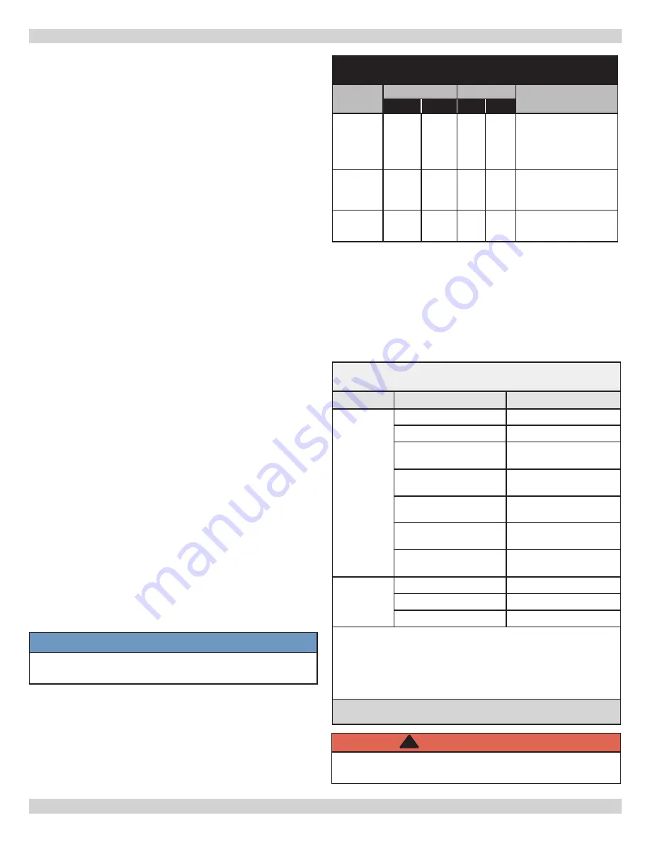
8 - COMBUSTION AIR AND VENT PIPE
8.1 Connections And Termination
Boilers for connection to gas vents or chimneys, vent
installations shall be in accordance with “Venting of
Equipment” of the National Fuel Gas Code, ANSI Z223.1/
NFPA 54, or “Venting Systems and Air Supply for
Appliances”, of the Natural Gas and Propane Installation
Code, CAN/CSA B149.1, or applicable provisions of local
building codes.
Provisions for combustion and ventilation air must be
in accordance with section, Air For Combustion and
Ventilation, of the National Fuel Gas Code, ANSI 2223.1/
NFPA54, National Gas and Propane Installation Code, CAN/
CGA-B 149.1, in absence of such requirements to the
Authority having jurisdiction.
Boilers require dedicated direct vent system. All air for
combustion is taken directly from outdoors through
combustion air intake pipe. All flue products are discharged
to outdoors through vent pipe.
1.
See
Figures 5 and 6 for two pipe combustion air
and vent pipe roof and sidewall termination. Roof
termination is preferred. Combustion air and vent pipes
must terminate together in same atmospheric pressure
zone as shown.
2.
Use of concentric vent termination see Figures 7-9for
proper setup.
3.
For Canadian installations all plastic venting material
must be listed to ULC S636.
4.
Construction through which vent and air intake pipes
may be installed is maximum 24 inches, minimum ¼”
thickness.
5.
See Table 5 for combustion air and vent pipe fittings
approved material and standards.
6.
Canada
construct all combustion air and vent pipes
for this unit of ULC S636 listed schedule-40 CPVC,
schedule-40 PVC, PVC-DWV or ABS-DWV pipe and pipe
cement. SDR pipe is not approved in Canada.
• First 3 feet (900mm) of venting must be readily
available for visual inspection.
• Specified primers and glues of certified vent
system must be from single manufacturer, and not
intermixed with other manufacturer’s vent system
parts.
• Components of the certified system must not be
interchanged with other vent systems, or unlisted pipe
and/or fittings.
NOTICE
Transition from 2” pipe to 3” pipe must be made in
vertical run.
7.
Boiler combustion air and vent pipe connections are 2”
but must increase to 3”. Due to potential for flue gas
temperatures above 155°F, first 30” of supplied vent
pipe is CPVC while remaining vent pipe can be PVC. Any
replacement of first 30” of vent pipe must be made with
CPVC.
8.
Covering non-metallic vent pipe and fittings with thermal
insulation shall be prohibited.
TABLE 4
Maximum Allowable Temperatures
Of Typical Non-Metallic Vent Material
Material
HDT
RTI
Standard
°F
°C
°F
°C
PVC
158
70
–
–
ASTM F 891 *
ASTM D2665 **
ASTM D1785 **
ASTM D2241 **
CPVC
210
100
–
–
ASTM D2846 **
ASTM F441 **
ASTM F442 **
ABS
180
82
–
–
ASTM D2661 ***
ASTM F628 ***
*
Allowable temperatures based on Classifications covered in ASTM
D4396 [Deflection Temperatures under Load (264psi) (1819 KPa)].
** Allowable temperatures based on Classifications covered in ASTM
D1784 [Deflection Temperatures under Load (264psi) (1819 KPa)].
*** Allowable temperatures based on Classifications covered in ASTM
D3965 [Deflection Temperatures under Load (264psi) (1819 KPa)].
Length of pipe is counted from end of supplied 2” CPVC
pipe exiting boiler. Termination is not counted in “Total
Equipment Length.”
Table 5 - Combustion air and vent pipe fittings
must conform with the following:
Item
Material
Standards
Vent Pipe
and Fittings
PVC schedule 40
ANSI/ASTM D1785
PVC - DWV
ANSI/ASTM D2665
CPVC schedule 40
ANSI/ASTM D1784/
F441
SDR-21 & SDR-26 PVC
ANSI/ASTM D2241
ABS-DWV
ANSI/ASTM D2661
Schedule 40ABS
ANSI/ASTM F628
PP (Polypropylene)
Pipe and Components
UL 1738
ULC S636-08
Pipe
Cement/
Primer
PVC
ANSI/ASTM D2564
CPVC
ANSI/ASTM F493
Schedule 40 ABS
ANSI/ASTM D2235
• IPEX is approved vent manufacturer in Canada listed
to ULC-S636.
• IPEX System 636 Cements and Primers are approved
in Canada listed to ULC-S636.
Use of cellular core PVC (ASTM F891), cellular core CPVC, or Radel
®
,
(Polyphenolsulfone) in venting systems shall be prohibited.
WARNING
Use of cellular core PVC for venting flue gas could
result in death, or serious injury.
!
12
Summary of Contents for Dunkirk Q95M-200
Page 2: ...1 DIMENSIONS OPENING FOR SAFETY RELIEF VALVE DISCHARGE PIPE 30 785mm 39 1 1m 18 458mm 2 ...
Page 27: ...APPENDIX A BOILER PIPING AND WIRING Electrical Wiring Diagram 27 ...
Page 49: ...49 NOTES ...
Page 50: ...50 NOTES ...
Page 51: ...51 Company Address Phone Company Name Tech Initials Service Performed Date SERVICE RECORD ...


